3-4
IM 04P01B01-17E
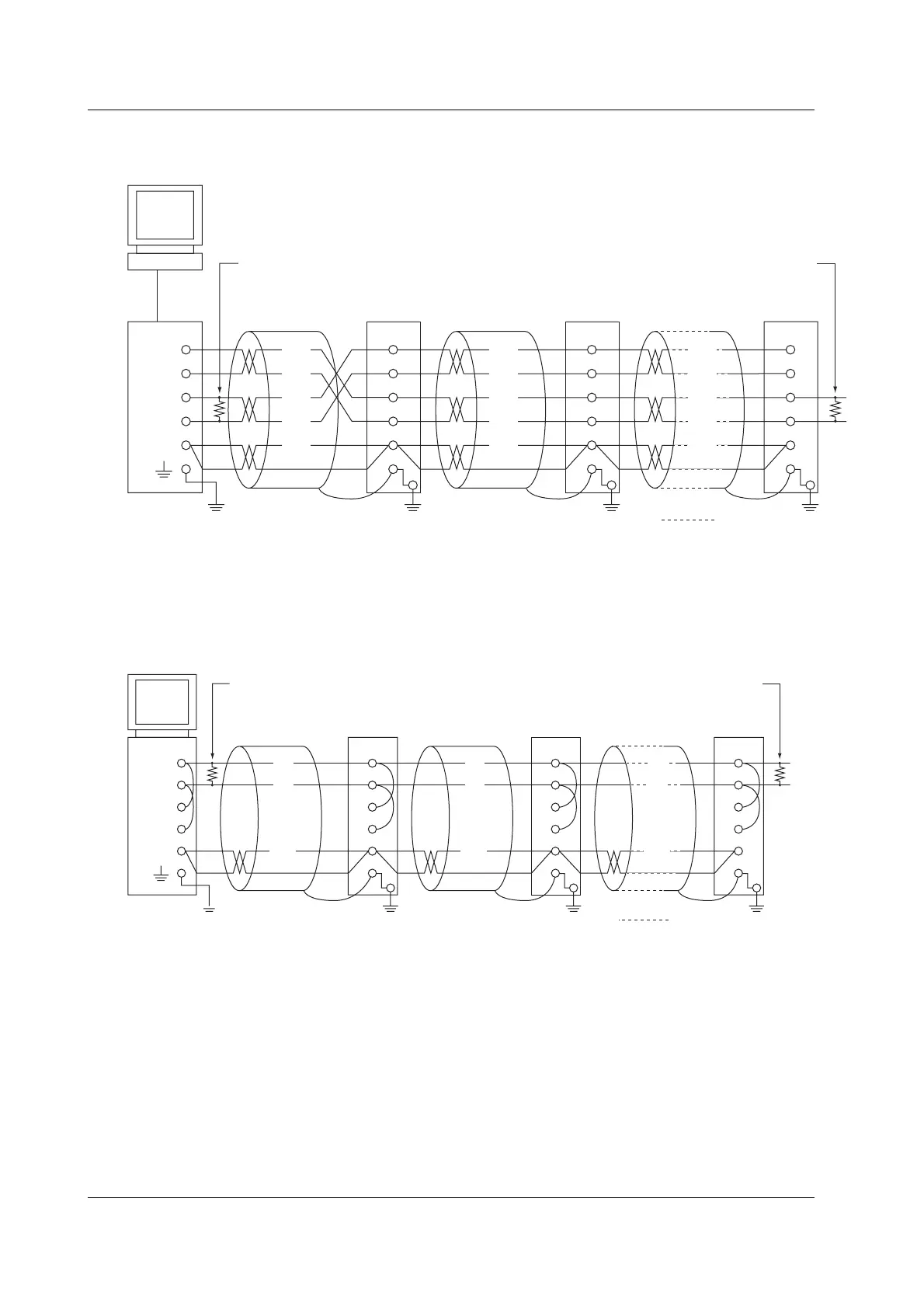
(The following figure illustrates the case when the host computer’s interface is RS-232.)
Terminator (external) 120 Ω 1/2W or greater
#1
Do not connect terminators to #1 through #n-1.
RS-422A/485
terminal on the
recorder
#2 #n
(#n ≤ 32)
Terminator (external)
SHIELD
RD( + )
RD( - )
TD( + )
TD( - )
FG
SG
RD B
RD A
SD B
SD A
Host
computer
Converter
(SG)
(RD B)
(RD A)
(SDB)
(SDA)
FG
SG
RD B
RD A
SD B
SD A
(SG)
(RD B)
(RD A)
(SDB)
(SDA)
FG
SG
RD B
RD A
SD B
SD A
(SG)
(RD B)
(RD A)
(SDB)
(SDA)
RS-232
• Two-Wire System
Connect the transmission and reception signals with the same polarity on the RS-
422A/485 terminal block. The two-wire system can be used only when using the
Modbus protocol.
Terminator (externally attached) 120 Ω, 1/2 W or more
#1
Do not connect terminator to #1 to #n–1
#2 #n
(#n ≤ 31)
Terminator (externally attached)
Host
computer
SG
RDB( + )
RDA( – )
SDB( + )
SDA( – )
FG
SG
RD B
RD A
SD B
SD A
(SG)
(B)
(A)
(B)
(A)
FG
SG
RD B
RD A
SD B
SD A
(SG)
FG
SG
RD B
RD A
SD B
SD A
(SG)
(B)
(A)
RS-422A/485
terminal on the
recorder
3.2
Terminal Arrangement and Signal Names and the Connection Procedure of the RS-422A/485 Communication Interface
 Loading...


