3-3
IM 04P01B01-17E
3
Using the RS-422A/485 Communication Interface (/C3 Option)
WARNING
To prevent the possibility of electric shock, connect the cables with the power
turned OFF.
Note
• Connect the RD pin to the SD (TD) pin on the PC (converter) end and the SD pin to the RD
pin on the PC end.
• The two-wire system can be used only when using the Modbus protocol.
Connection Example with a Host Computer
A connection can be made with a host computer having a RS-232, RS-422A, or RS-485
port.
• In the case of RS-232, a converter is used.
• For recommended converters, see “Serial Interface Converter” on the next page.
• The two-wire system can be used only when using the Modbus protocol. For the
configuration procedure, see section 3.5
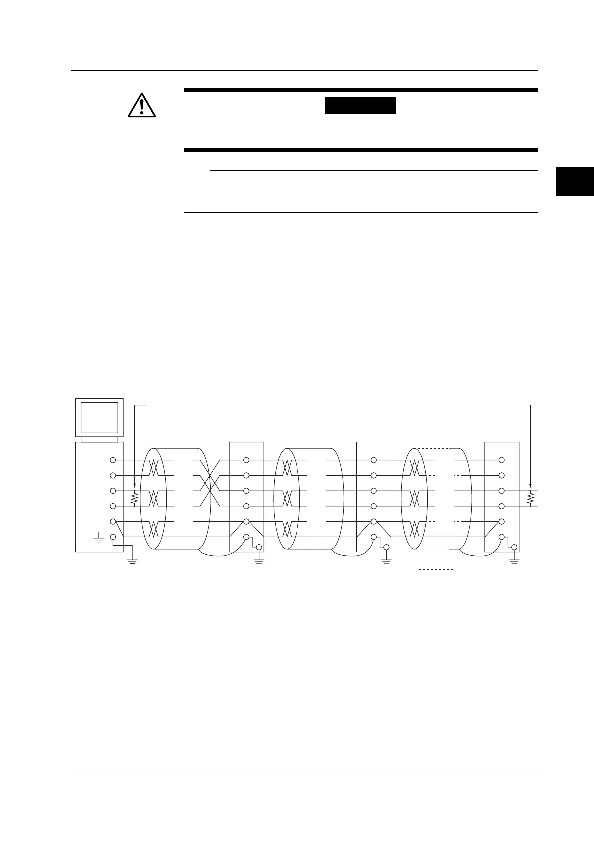
• Four-Wire System
Generally, a four-wire system is used to connect to a host computer. In the case of a
four-wire system, the transmission and reception lines need to be crossed over.
Terminator (external) 120 Ω 1/2W or greater
#1
Do not connect terminators to #1 through #n-1.
RS-422A/485
terminal on the
recorder
#2 #n
(#n ≤ 32)
Terminator (external)
Host
computer
SG
RDB( + )
RDA( - )
SDB( + )
SDA( - )
FG
SG
RD B
RD A
SD B
SD A
(SG)
(RD B)
(RD A)
(SDB)
(SDA)
FG
SG
RD B
RD A
SD B
SD A
(SG)
(RD B)
(RD A)
(SDB)
(SDA)
FG
SG
RD B
RD A
SD B
SD A
(SG)
(RD B)
(RD A)
(SDB)
(SDA)
3.2
Terminal Arrangement and Signal Names and the Connection Procedure of the RS-422A/485 Communication Interface
 Loading...


