C3-8
IM 34M06H62-02E 2nd Edition : June 2008-00
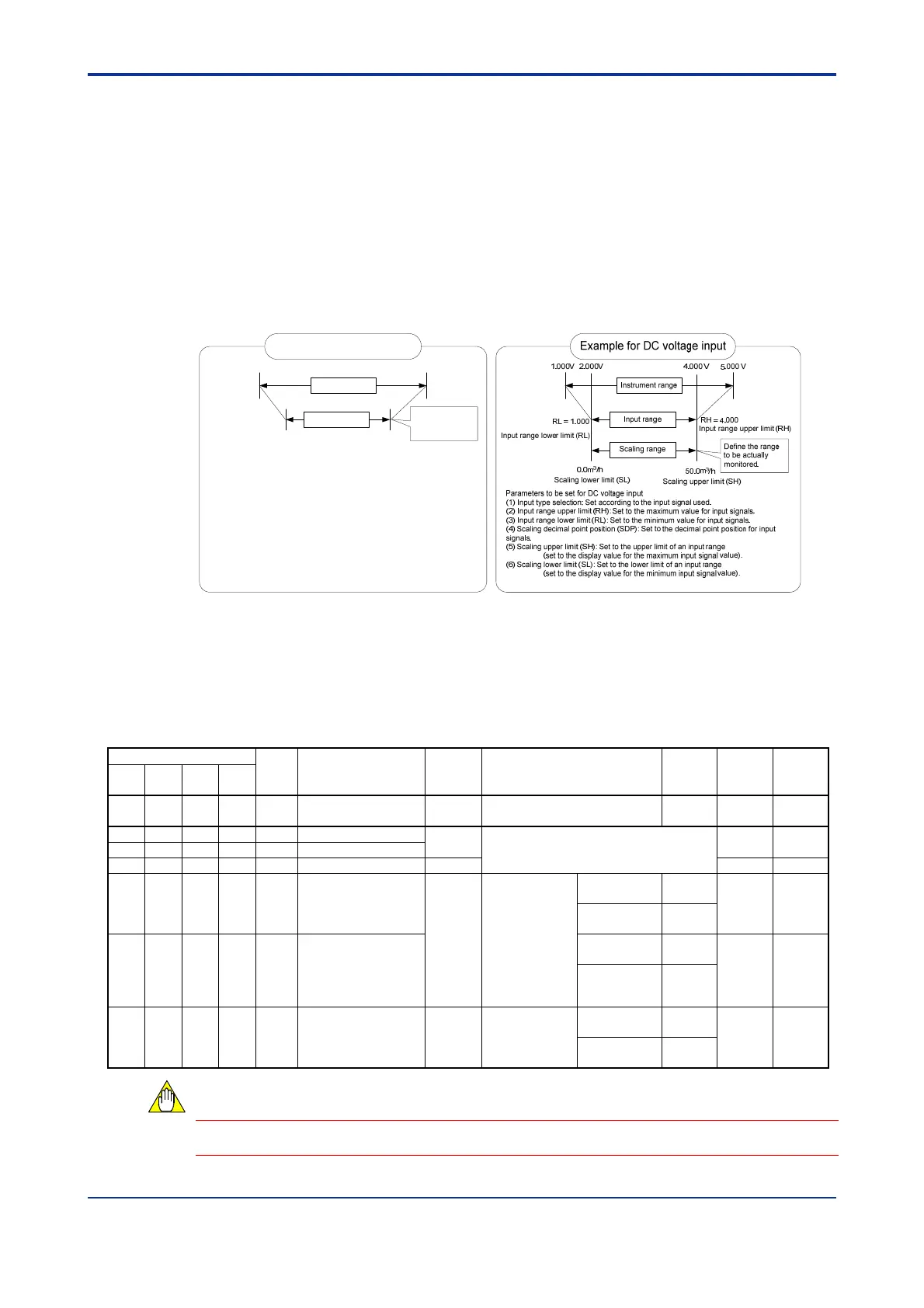
C3.3 Input Range Setting
For each instrument range selected using Input Type Selection, you may define an input
range, which is the actual temperature range to be monitored, by specifying upper (RH)
and lower (RL) limits within the instrument range. Some input types such as
thermocouple W, however, allow an input range that is wider than the instrument range.
For details, see Table C3.3, "Input Type Selection."
For example, to define an input range of 200.0-800.0C for an instrument range of -200.0
to 1200.0C for a thermocouple J input, set RH = 8000 and RL = 2000 (SH and SL are
equal to RH and RL for temperature input).
Likewise, to define an input range of 2-4 V for an instrument range of 1.000-5.000 V for
DC voltage input with a display range of 0.0-50.0, set RH = 4000, RL = 2000, SDP = 1,
SH = 500, and SL = 0.
Example for temperature input
-200.0°C 1200.0°C
Instrument range
Input range
200.0°C 800.0°C
Input range lower limit (RL)
Scaling lower limit (SL)
Input range upper limit (RH)
Scaling upper limit (SH)
Define the range
to be actually
monitored.
Parameters to be set for temperature input
(1) Input type selection: Set according to the sensor used.
(2) Input range upper limit (RH): Set to the max. value to be measured.
(3) Input range lower limit (RL): Set to the min. value to be measured.
Note: For temperature input, scaling uppler and lower limits (SH/SL) are
fixed at the input range upper and lower limits (RH/RL) respectively.
Figure C3.2 Examples of Input Range Setting
As shown in Figure C3.1, "Block Diagram of PV-related Functions," input values within a
defined input range undergo computation before it is provided as an input process value,
PVIN, to the system. For details on the computations performed, see Sections C3.9,
"Square Root Extraction," C3.7, "Broken-line Biasing," C3.8, "Fixed Biasing," and C3.10,
"Input Filtering."
Table C3.5 Parameters of Input-related Functions
Data Position Number
Symbol
Description Unit Data Range
Default
Value
Attribute
Stored
Loop
1
Loop
2
Loop
3
Loop
4
101 301 501 701 PVIN Input process value
Industrial
unit
-5.0% to 105.0% of
(SL to SH)
— RO —
143 343 543 743 RH Input range upper limit Industrial
unit
See Table A4.1 or C3.3, "Input Type
Selection."
RW
144 344 544 744 RL Input range lower limit
145 345 545 745 DEC.P Decimal point position None RO
146 346 546 746 SH Scaling upper limit
None
-30000 to 30000;
0 < SH - SL
30000.
Changeable only
for DC voltage
input with a
maximum
resolution of 14
bits (16384).
Thermocouple,
RTD
RH
RW
DC voltage
input
1000
147 347 547 747 SL Scaling lower limit
Thermocouple,
RTD
RL
RW
DC voltage
input
0
148 348 548 748 SDP
Scaling decimal point
position
None
0 to 4
Changeable only
for DC voltage
input
Thermocouple,
RTD
DEC.P
RW
DC voltage
input
1
Changing an input range does not improve accuracy or resolution.
CAUTION

 Loading...