B2-8
IM 34M06H62-02E 2nd Edition : June 2008-00
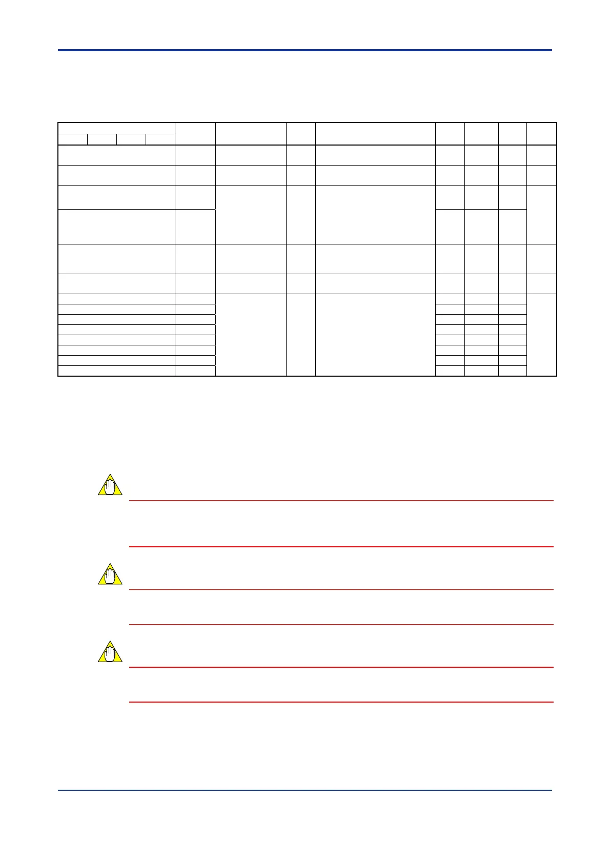
B2.2.7 Controller Parameters
Use these parameters to set up the basic operation of the module, such as input
sampling period and controller mode, on a module-wide basis.
Table B2.10 Controller Parameters
Data Position Number
Symbol Description Unit
Data Range
Default
Value
Attribute Stored
See
Also
Loop 1 Loop 2 Loop 3 Loop 4
81 FREQ
Power frequency
selection
*1
None
0: 50Hz
1: 60Hz
— RW
C3.2
82 SMP
Input sampling
period
*2
None
0: 100 ms
1: 200 ms
1 RW
B3.1.2
83 MD12
Controller mode None
0: Two single loops
1: Two-input changeover control
2: Cascade control
3: Single loop
(odd-numbered disabled)
4: Both loops disabled
0 RW
C1.
84 MD34 0 RW
87 OUTPUT
Output type
selection
*3
None
Each terminal may be
configured for either open
collector or analog output.
0 RW
C2.2
90 REV
Firmware
revision
None —
— — — —
91 OUTSEL1
Output terminal
selection
*4
None
1-4: Heating outputs 1-4
11-14: Cooling outputs 1-4
21-28: Output preset values 1-8
*3
1 RW C2.3
92 OUTSEL2 2 RW
93 OUTSEL3 3 RW
94 OUTSEL4 4 RW
95 OUTSEL5 11 RW
96 OUTSEL6 12 RW
97 OUTSEL7 13 RW
98 OUTSEL8 14 RW
*1 The power frequency is set by default to the value set with the power frequency selector switch SW1-2. It can also be
selected with SW1-2. For details on how to do so, see Section A4.1, “Selecting Input Types and Power Frequency”. If the
power frequency is set using a hardware switch, the setting cannot be changed by software.
*2 This preset value imposes some restrictions on the number of loops that can be used. A value of 100ms allows up to 2
loops to be used, whilst a value of 200ms allows up to 4 loops to be used.
*3 This parameter is available only with F3CU04-1S. After selecting “Output preset value n” using the Output Terminal
Selection parameter, you must also specify a corresponding Output Preset Value (AOUTn) parameter value. (see also
Section B2.2.2, "Analog Output Settings").
*4 The F3CU04-0S module has only four output terminals. Thus, registers OUTSEL 5-8 are disabled and data range 21-28
is ignored.
The controller parameters must be enabled before any written content can take effect.
For details on how to enable these parameters, see Section B2.3, “How to Enable
Settings.”
Changing a controller parameter initializes other related parameters. Always set
controller parameters before setting I/O parameters and operation parameters.
You must observe some precautions when writing to the module. For details, see Section
B1.3, “Writing and Reading after Powering On.”
CAUTION
CAUTION
CAUTION

 Loading...