B2-13
IM 34M06H62-02E 2nd Edition : June 2008-00
B2.2.10 I/O Parameters
The I/O parameters are classified into two categories: required and optional. The required
setup parameters must always be checked and set, and the optional setup parameters
may be set as required. All I/O parameters apply to individual loops.
The required setup parameters are input type selection and control type selection
parameters. They are the most basic loop setup elements.
The optional setup parameters include PV-related parameters for changing the input range
and selecting a burnout operation, as well as parameters that are used only in two-input
changeover mode.
I/O Type Settings
These parameters are used to select input types (ranges) and output control types for
individual loops. These parameters are the most basic loop setup elements.
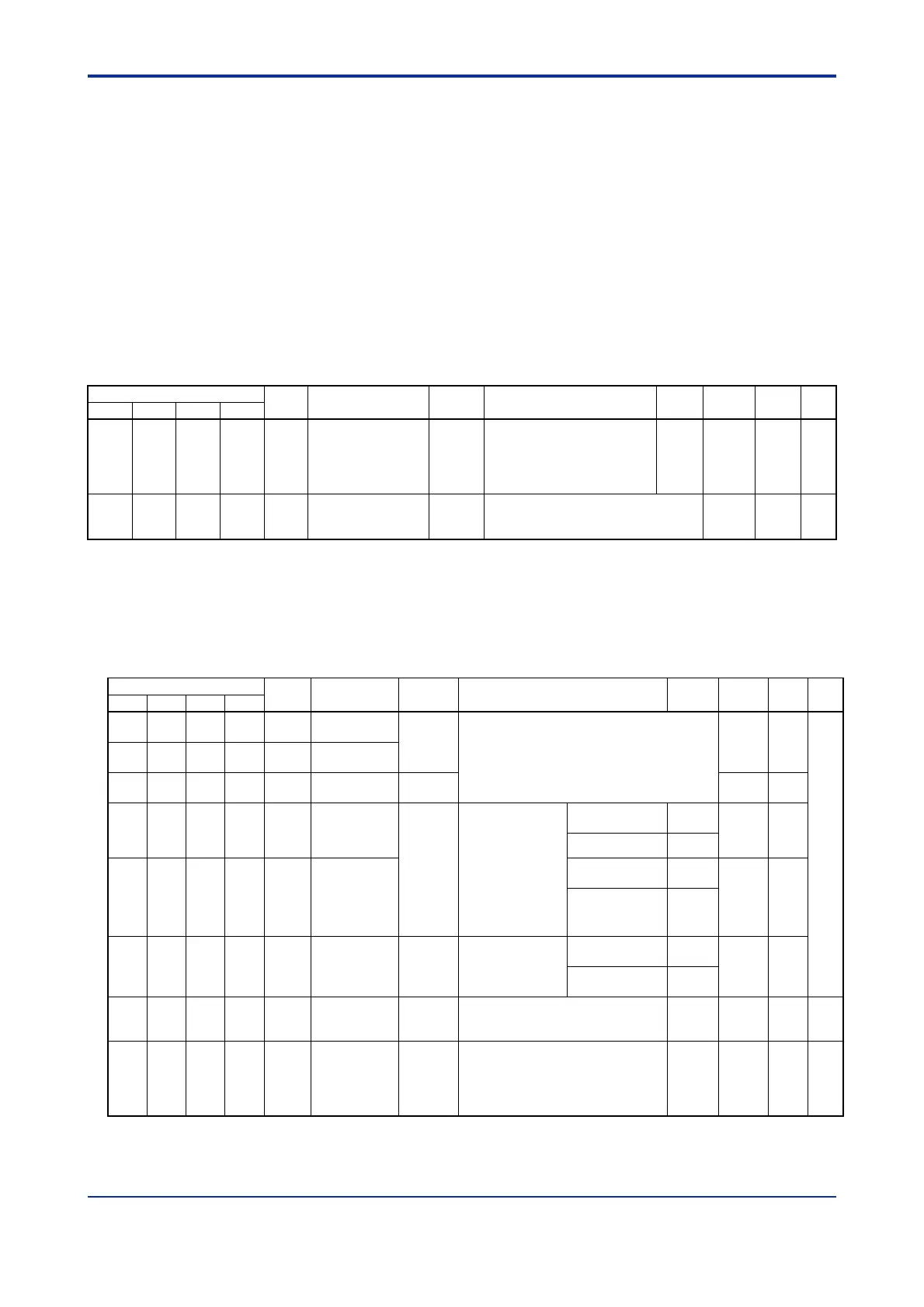
Table B2.17 I/O Parameters (1/3)
Data Position Number
Symbol
Description Unit Data Range
Default
Value
Attribute Stored
See
Also
Loop 1 Loop 2 Loop 3 Loop 4
141 341 541 741 OT
Control type
selection
None
0: PID control
1: ON/OFF control
2: Heating/cooling PID control
3: Heating/cooling ON/OFF
control
0 RW C2.1
142 342 542 742 IN Input type selection
*1
None
1-31, 33-56
For details, see Table A4.1, "Input Type
Selection."
RW C3.1
*1 To select input type by software, you must set the input type selector switches to “set by software”, that is, “SW5=0 and
SW1-4=OFF” (also see Section A4.1, "Selecting Input Types and Power Frequency").
Input Range Settings
Use these parameters to set up the input of individual loops, as required, such as
changing the input range or selecting an appropriate burnout operation.
Table B2.17 I/O Parameters (2/3)
Data Position Number
Symbol Description Unit Data Range
Default
Value
Attribute
Stored
See
Also
Loop 1
Loop 2
Loop 3
Loop 4
143 343 543 743 RH
Input range
upper limit
Industrial
unit
See Table A4.1, “Input Type Selection”.
RW
C3.3
144 344 544 744 RL
Input range
lower limit
145 345 545 745 DEC.P
Decimal point
position
None RO
146 346 546 746 SH
Scaling upper
limit
None
-30000 to 30000;
0 < SH - SL
30000.
Changeable only
for DC voltage
input with a
maximum
resolution of 14
bits (16384).
Thermocouple
input, RTD input
RH
RW
DC voltage input 1000
147 347 547 747 SL
Scaling lower
limit
Thermocouple
input, RTD input
RL
RW
DC voltage input 0
148 348 548 748 SDP
Scaling
decimal point
position
None
0 to 4
Changeable only
for DC voltage
input
Thermocouple
input, RTD input
DEC.P
RW
DC voltage input 1
149 349 549 749 RJC
Reference
junction
compensation
None
0: Fixed value
1: ON 1 RW C3.6
150 350 550 750 BSL
Burnout
selection
None
0: OFF
1: Up Scale
2: Down Scale
(Valid for Thermocouple input and
RTD input)
1 RW C3.5

 Loading...