B3-2
IM 34M06H62-02E 2nd Edition : June 2008-00
B3.1 Setting Controller Parameters
Controller parameters are used for performing module-wide setup to suit the operating
environment and mode of use. They define the most basic operations of the module.
The setup elements are described in Sections B3.1.1, “Power Frequency Selection”,
B3.1.2, “Input Sampling Period,” B3.1.3, “Controller Mode” and B3.1.4, “Setting Output
Terminals.” You should set these parameters to match the operating and usage
environment. The controller parameters must be enabled before any written content can
take effect. For details on how to enable parameter settings, see Section B2.3, “How to
Enable Settings.”
Changing a controller parameter initializes the parameters of the module. Always set
controller parameters before other parameters.
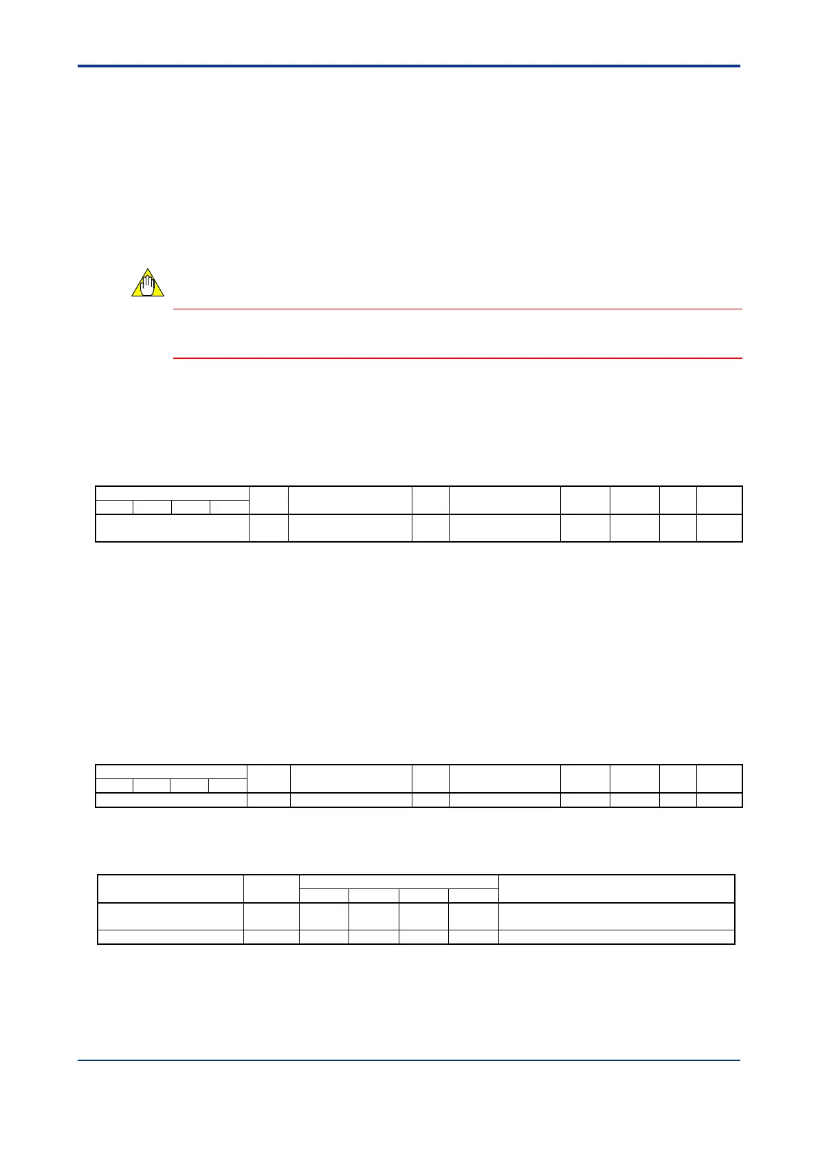
B3.1.1 Power Frequency Selection
Use this parameter to select a power frequency that matches the power supply
environment.
Table B3.1 Power Frequency Selection
Data Position Number
Symbol
Description Unit
Data Range
Default
Value
Attribute Stored
See Also
Loop 1
Loop 2
Loop 3
Loop 4
81 FREQ
Power frequency
selection
*1
None 0: 50Hz, 1: 60Hz 0 RW
*1
C3.2
*1 The power frequency can also be selected using a hardware switch. For details on how to do so, see Section A4.1,
“Selecting Input Types and Power Frequency”. If the power frequency is set using the hardware switch, the setting
cannot be changed by software.
Selecting an appropriate power frequency reduces interference of common mode noise
from the power supply on input signals.
B3.1.2 Input Sampling Period
This parameter sets the input sampling period. Beware that a short sampling period
restricts the number of available loops.
Table B3.2 Input Sampling Period
Data Position Number
Symbol Description Unit
Data Range
Default
Value
Attribute Stored
See Also
Loop 1 Loop 2 Loop 3 Loop 4
82 SMP Input Sampling period
1
None 0: 100 ms, 1: 200 ms 1 RW —
*1 This setting restricts the number of available loops. A value of 100ms allows up to 2 loops to be used, whilst a value of
200ms allows up to 4 loops to be used. Table B3.3 lists the usable loops for different preset values.
Table B3.3 Mapping between Input Sampling Period and Usable Loops
Input Sampling Period
Preset
Value
Usable Loops
*1
Remarks
1 2
3
4
100 ms 0 — —
The output function of each loop is always
available, even for loops 3 and 4.
200 ms 1 Default Value
*1 ‘’ : usable; ‘— ‘: not usable.
CAUTION

 Loading...