C10-2
IM 34M06H62-02E 2nd Edition : June 2008-00
C10.1 How to Check for Errors
When an error occurs, the ERR LED lights up, and the Operating Status (RUN.STUS)
and Error Status (ERR.STUS) registers indicate details of the error. For details on how to
identify and handle errors, see PART-D, “Troubleshooting”.
C10.2 List of Error Statuses
When an error occurs, the Operating Status (RUN.STUS) and Error Status (ERR.STUS)
registers provide error information by turning on relevant bits.
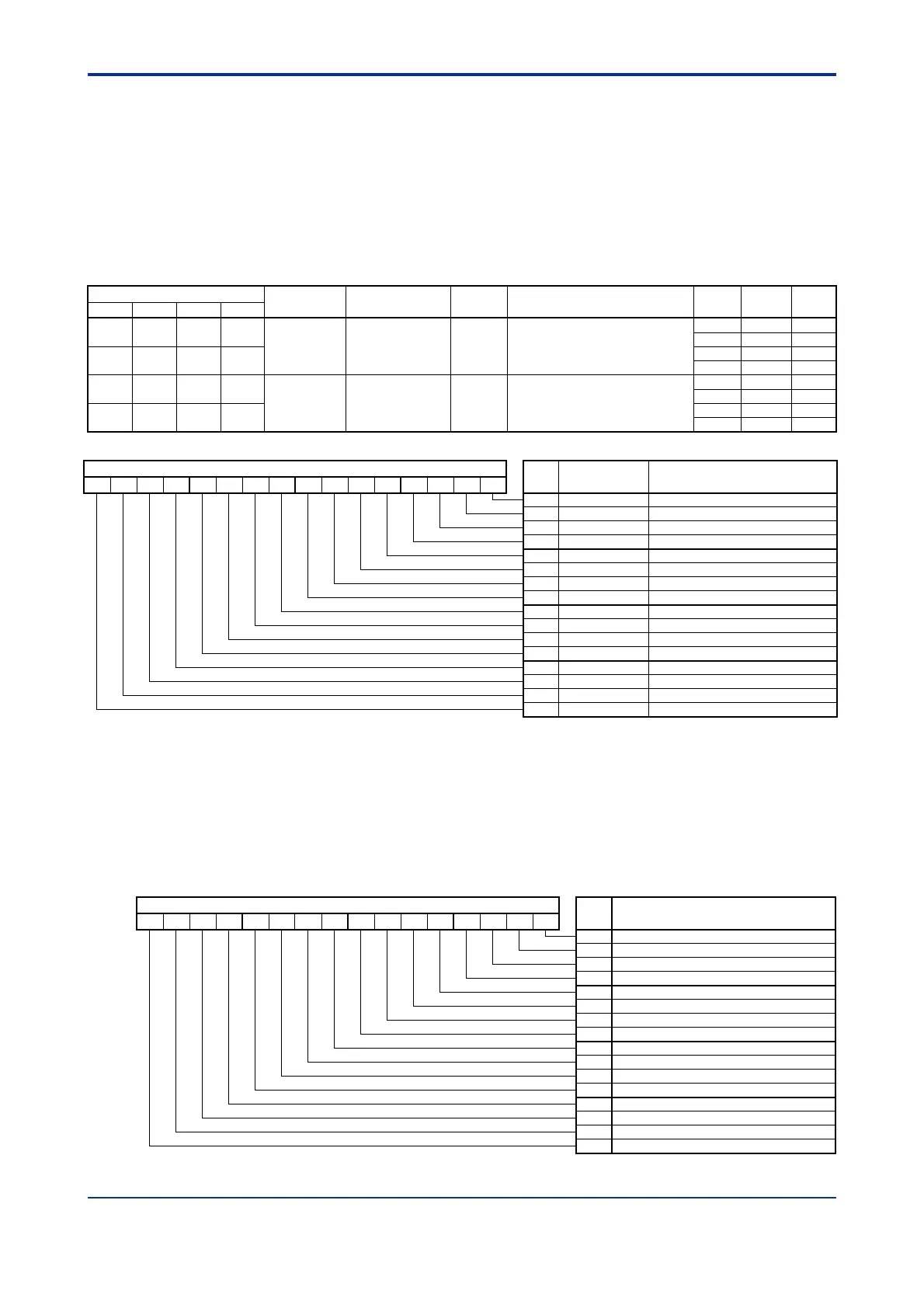
Table C10.1 Error-related Parameters
Data Position Number
Symbol Description
Unit Data Range
Default
Value
Attribute
Stored
Loop 1 Loop 2 Loop 3 Loop 4
41 42 43 44
RUN.STUS Operating status None
On/off for individual bits. For
details, see Table C10.2.
— RO —
— RO —
108 308 508 708
— RO —
— RO —
51 52 53 54
ERR.STUS Error status None
On/off for individual bits. For
details, see Table C10.3.
— RO —
— RO —
110 310 510 710
— RO —
— RO —
Table C10.2 Operating Status
RUN.STUS
Bit
pos.
Symbol Description
15 14 13 12 11 1
9 8
7
5 4
3
2
1
0
RUN/STP
0: Sto
1: Run
1
UT/MAN
0: Automati
1: Manual
2
CAS
1: Cascade
3
RMT/LOC
0: Local 1: Remote
4
EXPV/PV
0: Normal in
ut 1: External In
ut
5
EXOUT/OUT
0: Normal out
ut 1: External Out
ut
6
―
7
―
8
B.OUT
1: PVIN burnout
9
+OVER
1: PVIN +OVER
10
-
OVER
1: PVIN -OVER
11
B.OUT
1: PV burnout
12
+OVER
1: PV +OVER
13
-
OVER
1: PV -OVER
14
―
15
FUNC.ERR
1: Error detected
PVIN+OVER occurs when input exceeds 105% of the input range, and PVIN-OVER
occurs when input is below -5% of the input range. PV+OVER and PV-OVER are
equivalent to PVIN+OVER and PVIN-OVER in Single-input mode. In Two-input
Changeover mode, PV+OVER occurs when input exceeds 105% of the PV input range of
the even loop, and PV-OVER occurs when input is below -5% of the PV input range of
the even loop. For details on PVIN burnout and PV burnout, see Section C3.5, "Burnout
Detection." When the FUNC.ERR bit of the RUN.STUS parameter is set, detailed error
information is provided in the ERR.STUS parameter.
Table C10.3 Error Status
ERR.STUS
Bit
pos.
Usage
15 14 13 12 11 1
9 8 7
5
4
3
2
1
0
―
1
S
stem data error
2
Calibration value error
3
Controller or I/O
arameter error
4
O
eration
arameter error
5
D converter error
6
RJC error
7
EEPROM error
8
―
9
―
10
―
11
―
12
―
13
―
14
―
15
―

 Loading...