C2-9
IM 34M06H62-02E 2nd Edition : June 2008-00
C2.4.2 PID Control Output
In PID control output, the module continuously adjusts its output according to the
deviation between the control set point (CSP) and the PV. To select PID control output,
set the Control Type Selection (OT) parameter to 0. For details, see Section C2.1,
“Control Type Selection."
There are two types of PID control output, namely, time-proportional PID control output
and continuous PID control output, which can be specified for each terminal. To configure
a terminal for time-proportional PID control, set the Output Type Selection (OUTPUT)
parameter to Open Collector. To configure a terminal for continuous PID control, set the
Output Type Selection (OUTPUT) parameter to Analog Output. For details on the control
and computation function and various PID parameters, see Section C6, "Control and
Computation Function."
Time-proportional PID Control Output
In time-proportional PID control mode, the PID computation result, HOUT, is output after
it is converted to ON/OFF duty cycle as defined by the Cycle Time (CT) parameter. 100%
duty cycle means “always on”, 0% duty cycle means “always off”, and 25% duty cycle
means “on for 25% and off for 75% of the cycle time”. In heating/cooling control
operation, the PID computation result, COUT, is output after it is converted to ON/OFF
duty cycle as defined by the Cooling Cycle Time (CTc) parameter.
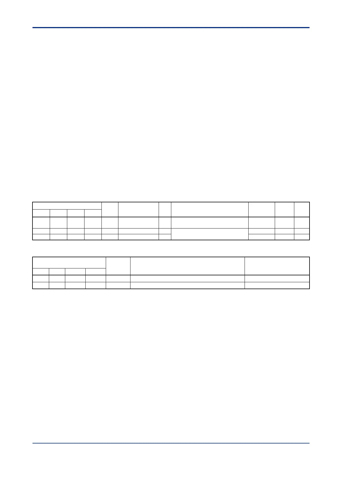
Table C2.8 I/O Registers Related to Time-proportional PID Control
Data Position Number
Symbol
Description Unit
Data Range
Default
Value
Attribute
Stored
Loop 1 Loop 2 Loop 3 Loop 4
104 304 504 704 HOUT Control output %
OL to OH: for single output
0 to OH: for heating/cooling output
— RO —
191 391 591 791 CT Cycle time s
5 to 1200 (0.5 to 120.0 s)
300 RW
192 392 592 792 CTc Cooling cycle time s 300 RW
Table C2.9 Input Registers Related to Time-proportional PID Control
Input Relay Number
Xnn
*1
Symbol Description Data Range
Loop 1 Loop 2 Loop 3 Loop 4
X05 X13 X21 X29 HOUT.R Heating control output 0: OFF 1: ON
X06 X14 X221 X30 COUT.R Cooling control output 0: OFF 1: ON
*1 denotes the slot number where the module is installed.
A smaller Cycle Time (CT) parameter value means finer control. However, too short a
cycle time means frequent ON/OFF operations, which may shorten the life of a relay,
which is used as an output element. We recommend setting CT to around 10-30 s when
using mechanical relay output.
The resolution of the CT setting is 0.5 s. If you specify an intermediate value, the value
will be truncated appropriately. For example, if you specify 20.6 s for CT, the value is
treated as 20.5 s.

 Loading...