B3-8
IM 34M06H62-02E 2nd Edition : June 2008-00
B3.2 Setting I/O Parameters
I/O parameters are classified into two categories: required I/O parameters that must be
checked and set, and optional I/O parameters that can be set as required. All I/O
parameters apply to individual loops.
The required parameters are described in Sections B3.2.1, “Input Type Selection,” and
B3.2.2, "Control Type Selection."
Optional I/O parameters are used for changing the input range, for selecting burnout
detection, as well as for setting the upper and lower limits of the PV range when using
Two-input Changeover control.
For details on functions selectable with optional I/O parameters, see Chapter C3,
“PV-related Functions”.
I/O parameters must be enabled before any written content can take effect. For details on
how to enable parameter settings, see Section B2.3, “How to Enable Settings.”
Changing an I/O parameter initializes operation parameters and other related I/O
parameters. Therefore, always set I/O parameters before setting operation parameters.
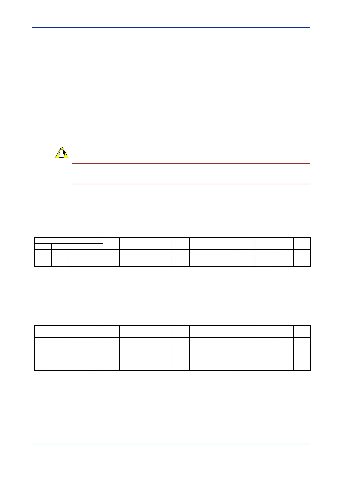
B3.2.1 Input Type Selection
These parameters specify the input type of individual loops. Select a preset value that
matches the temperature range and voltage range of the sensor to be used.
Table B3.8 Input Type Selection
Data Position Number
Symbol Description Unit Data Range
Default
Value
Attribute Stored
See
Also
Loop1 Loop 2 Loop 3 Loop 4
142 342 542 742 IN Input type selection
*1
None
1 to 31, 33 to 56
For details, see Table A4.1,
"Input Type Selection."
RW
*1
C3.1
*1 You can also select input types using hardware switches as described in Section A4.1, "Selecting Input Types and Power
Frequency." If a selection is made using a hardware switch, the setting cannot be changed by software.
B3.2.2 Control Type Selection
This parameter specifies the control type for each loop.
Table B3.9 Control Type Selection
Data Position Number
Symbol Description Unit Data Range
Default
Value
Attribute Stored
See
Also
Loop 1 Loop 2 Loop 3 Loop 4
141 341 541 741 OT Control type selection None
0: PID control
1: ON/OFF control
2: Heating/cooling
PID control
3: Heating/cooling
ON/OFF control
0 RW C2.1
For details on how to assign a specific output type to a specific output terminal, see
Section B3.1.4, "Setting Output Terminals." See also Section C2, "Output-related
Functions."
CAUTION

 Loading...