B2-2
IM 34M06H62-02E 2nd Edition : June 2008-00
B2.2 Types of Registers
This module is provided with input/output data registers for configuring module operation
and reading operation status. Registers for configuration include basic setup elements,
as well as supplementary setup elements for supporting various modes of operation. Set
these registers appropriately to suit the intended usage. In addition to registers for
reading the status of individual loops, other registers are provided to store process data
for all loops, arranged sequentially within a data area. Table B2.2 lists the categories of
I/O data registers provided, along with a short description for each category. Table B2.3
and subsequent tables list the I/O data registers by category.
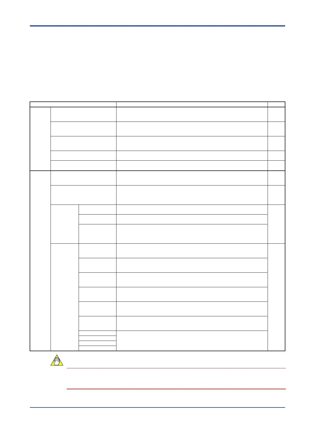
Table B2.2 Structural Overview of I/O Data Registers
Category Description
See Also
Common Common process data These are basic process-related data for all loops, comprising
constantly-monitored process-related data including PV, control set point
and control output.
B2.2.1
Analog output settings These parameters are only available for F3CU04-1S. They can be used to
specify analog output of a specific value (4-20 mA) for any output terminal
not used for control output.
B2.2.2
Setup control parameters Use these parameters to enable various settings, required when controller
parameters or I/O parameters are updated.
For details on the procedure, see Section B2.3, “How to Enable Settings.”
B2.2.3
B2.3
Function control parameters Use these parameters to configure the operation of module functions on a
module-wide basis.
B2.2.4
Controller parameters Use these parameters to set up the basic operation of the module, such as
input sampling period and controller mode, on a module-wide basis.
B2.2.5
B3.1
Loops
1 to 4
Process data These are process-related data for each loop.
They include PV, control set point, control output, error status, etc., which
can be used for monitoring the operation of the module.
B2.2.8
Operation control parameters Use these parameters to control the operation of individual loops. They
control run/stop, automatic/manual/cascade, auto-tuning and other
operation control modes, as well as manual output and other operation
control parameters.
B2.2.9
I/O
parameters
I/O type settings Use these parameters to select input and output types for individual loops.
These are the most basic loop-specific parameters.
B2.2.10
B3.2
Input range
settings
Use these parameters to change input ranges and other input-related
settings or select burnout operations for individual loops.
PV range settings These parameters are only valid in the two-input changeover mode, and
are used for defining the PV range in two-input changeover control.
By default, the PV range follows the input range of the even-numbered
loop.
Operation
parameters
Two-input
changeover
function settings
Use these parameters to perform setup when using the two-input
changeover mode. They can be used for setting the changeover method
and temperature.
B3.3
SP-related
function settings
Use these parameters to define set points for individual loops, as required.
They can be used for setting upper and lower input limits, rate-of-change,
and tracking.
PV-related
function settings
Use these parameters to perform PV-related setup for individual loops, as
required. They can be used for configuring PV correction, square root
extraction and input filtering.
Operation-related
function settings
Use these parameters to configure control operation for individual loops, as
required. They can be used to set up dynamic auto-tuning, the “super”
function, control mode, and other control-related functions.
Output-related
function settings
Use these parameters to configure control output for individual loops, as
required. They can be used for setting control output cycle time and
rate-of-change limits.
Alarm-related
function settings
Use these parameters to set up the operation of the alarm functions for
individual loops as required. They can be used to set the alarm type,
hysteresis, and ON delay timer.
PID paramete
s 1 Use these parameters to configure PID control-related functions for
individual loops. They can be used for specifying set points, alarm preset
values, proportional band, integral time, and derivative time.
Up to four parameter groups can be defined for each loop.
PID paramete
s 2
PID paramete
s 3
PID paramete
s 4
Controller parameters and I/O parameters must be enabled before any written content
can take effect. For details on how to enable such parameters, see Section B2.3, “How to
Enable Settings.”
CAUTION

 Loading...