B2-14
IM 34M06H62-02E 2nd Edition : June 2008-00
PV Range Settings
These parameters are only valid in Two-input Changeover mode, and are used for
defining the input range in Two-input Changeover mode. By default, the PV range follows
the input range of the even-numbered loop.
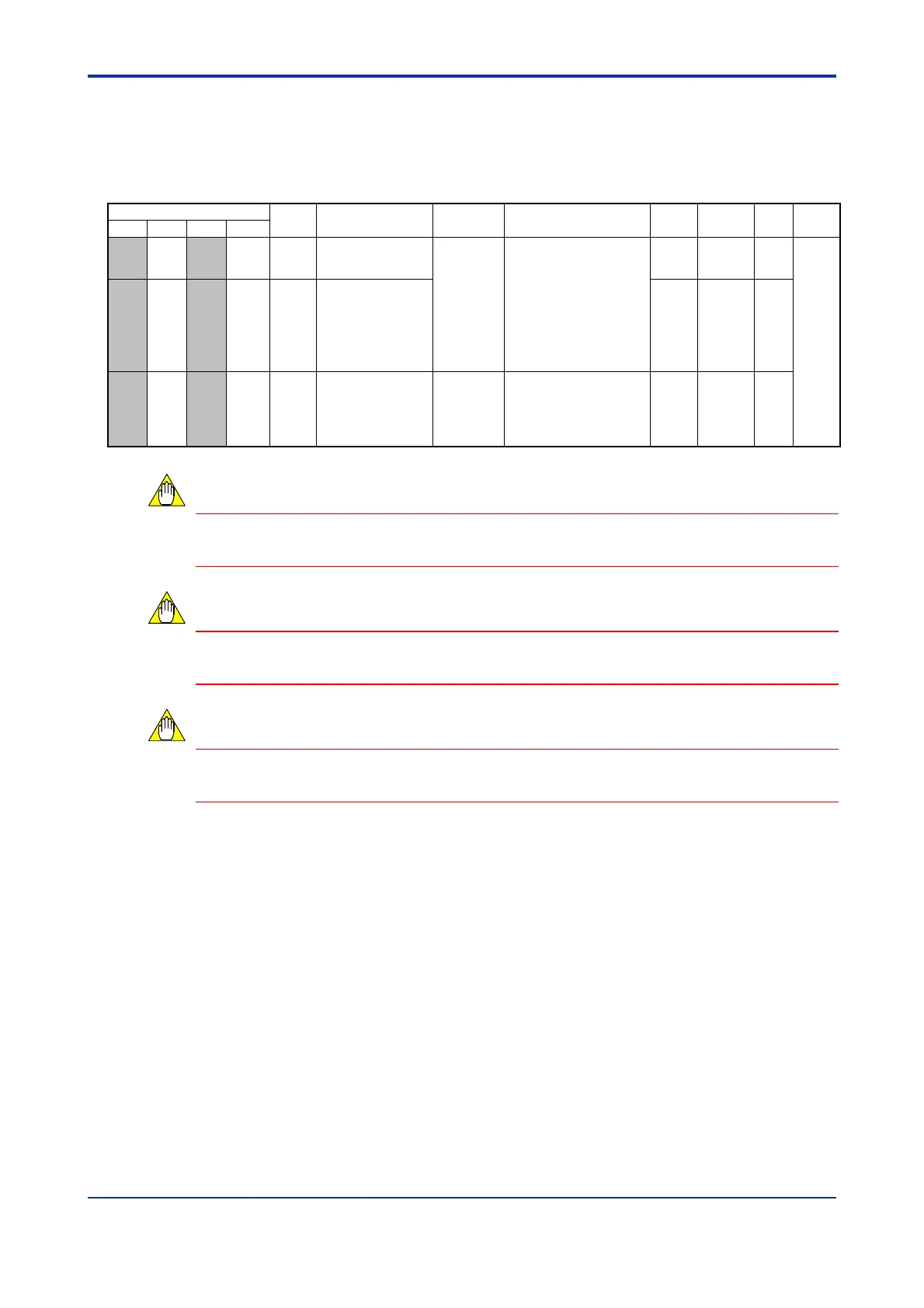
Table B2.17 I/O Parameters (3/3)
Data Position Number
Symbol Description Unit Data Range
Default
Value
Attribute Stored
See
Also
Loop 1 Loop 2 Loop 3 Loop 4
— 351 — 751 PRH
PV range upper
limit
Industrial
unit
- 30000 to 30000;
0 < (PRH - PRL)
30000.
Changeable only for
even-numbered loops
in two-input
changeover mode with
a maximum resolution
of 14 bits (16384).
SH RW
C3.4
— 352 — 752 PRL
PV range lower
limit
SL RW
— 353 — 753 PDP
PV range decimal
point position
None
0 to 4
Changeable only for
even-numbered loops
in two-input
changeover mode
SDP RW
I/O parameters must be enabled before any written content can take effect. For details on
how to enable such parameters, see Section B2.3, “How to Enable Settings.”
Changing an I/O parameter initializes operation parameters. Therefore, always set I/O
parameters before setting operation parameters.
You must observe some precautions when writing to the module. For details, see Section
B1.3, “Writing and Reading after Powering On.”
CAUTION
CAUTION
CAUTION

 Loading...