IM 253401-01E
2-3
2
Nomenclature, Keys and Displays
2.2 Operation Keys and Function/Element Display
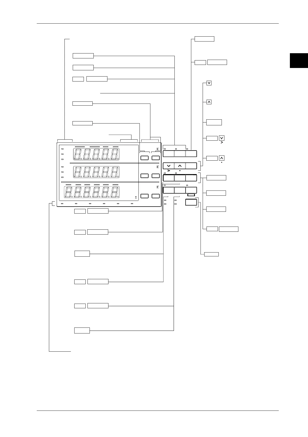
WT130 (253502, 253503): Operation keys and function / element display
SCALING
AVG FILTER
STORE
RECALL
HARMONICS
SAMPLE
V OVER
A OVER
MODE
RMS
V MEAN
DC
A
B
C
hour
hour
min
min sec
VVA
m
Ak
var
MW
TIME
VPF
m
Ak
deg
MW
%
FUNCTION
AUTO AUTO
MODE
1Φ3W
VHz
m
Ak
h
MW
TRIG
V RANGE A RANGE HOLD
ENTER
INTEGRATOR
START
HARMONICS MEMORY INTEG SET
STOP RESET
REMOTE
INTERFACE OUT PUT
LOCAL
SETUP
h
SHIFT
WIRING
3Φ4W
3Φ3W
3V3A
ELEMENT
123
FUNCTION ELEMENT
123
FUNCTION ELEMENT
123
WIRING
FUNCTION
ELEMENT
Function/unit display
Sets the displayed function (Ch. 5, 6)
Sets the connection format matching the
connection to the voltage/current input
terminals at the rear (page 3-15)
Sets the input element for
measurement/integration. The corresponding
indicator will light up (Ch. 5, 6)
Indicators for operating functions
When a function is set and in operation, this indicator will light up
SHIFT
HARMONICS
START
Shows the setting menu for harmonics ON/OFF, PLL
source, and element selection (Ch. 8)
SHIFT
MEMORY
STOP
Shows the setting menu for storing/recalling
measurement data and set-up information (Ch. 9)
SETUP
SETUP
SHIFT
INTERFACE
SHIFT
OUTPUT
When the REMOTE indicator is lit, the remote
function will be canceled. When the REMOTE
indicator is not lit, the setting menu for
communication/printing will appear
Shows the setting menu for
communication/printing (Ch. 11, 12)
Shows the setting menu for communication output items, D/A
output, plotter / printer output and comparator output (Ch. 10
to 12)
For settings such as initializing settings, filter, average,
scaling and ext. sensor input (Ch. 4)
LOCAL
LOCAL
Starts integration
Integration value and elapsed time of
integration are set to zero(0)
Shows the setting menu for integration
mode/time, and rated integration time (Ch.7)
RESET
INTEG SET
RESET
STOP
START
SHIFT
ENTER
For decreasing the voltage/current range,
and for setting of functions/values
For increasing the voltage/current range,
and for setting of functions/values
For verifying the set range/function/value
Moves the cursor of a value from left to right
Moves the decimal point from left to right
SHIFT
SHIFT
Keeps the displayed value, and the HOLD
indicator will light up. Pressing once again will
result in canceling HOLD
When in the HOLD situation this results in
updating the displayed value
HOLD
SHIFT TRIG
HOLD
SHIFT
MODE
V RANGE
A RANGE
V RANGE
Shows the voltage range setting menu (page 4-4)
Shows the current range setting menu (page 4-4, 4-8)
Switches between modes (page 4-1)
AUTO indicator
Lights up when range is AUTO
Indicators for operation conditions
Shows sampling, voltage/current overrange and
measurement mode
Stops integration
 Loading...


