App-7
IM WT310E-01EN
Appendix
App
To determine the mean value, the average is taken over 1 period of absolute values, because simply
taking the average over 1 period of the sine wave results in a value of zero. With Imn as the mean
valueoftheinstantaneouscurrenti(whichisequaltoImsinωt):
Imn=The mean of i over one period =
1
π
0
2π
i dωt
Im
2
=
2
π
These relationships also apply to sinusoidal voltages.
The maximum value, rms value, and mean value of a sinusoidal alternating current are related as
shown below. The crest factor and form factor are used to define the tendency of an AC waveform.
Crest factor =
Maximum value
rms value
Form factor =
rms value
Mean value
Vector Display of Alternating Current
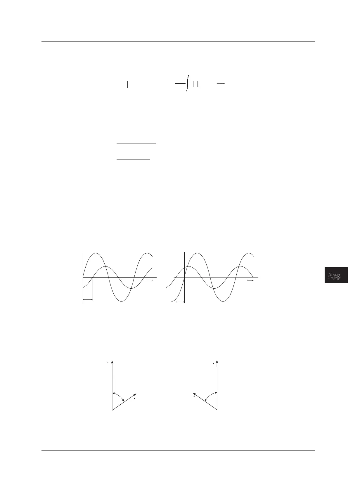
In general, instantaneous voltage and current values are expressed using the equations listed below.
Voltage:u=Umsinωt
Current:i=Imsin(ωt–
Φ
)
The time offset between the voltage and current is called the phasedifference,andΦisthephase
angle. The time offset is mainly caused by the load that the power is supplied to. In general, the phase
difference is zero when the load is purely resistive. The current lags the voltage when the load is
inductive (is coiled). The current leads the voltage when the load is capacitive.
0
π
2π
i
u
ωt
Φ
When the current lags the voltage
0
π
2π
i
u
ωt
Φ
When the current leads the voltage
A vector display is used to clearly convey the magnitude and phase relationships between the voltage
and current. A positive phase angle is represented by a counterclockwise angle with respect to the
vertical axis.
Normally, a dot is placed above the symbol representing a quantity to explicitly indicate that it is a
vector. The magnitude of a vector represents the rms value.
Φ
U
I
When the current lags the voltage
Φ
U
I
When the current leads the voltage
Appendix 2 Power Basics (Power, harmonics, and AC RLC circuits)

 Loading...


