JOHNSON CONTROLS
29
SECTION 3 – HANDLING, STORAGE, INSTALLATION AND REASSEMBLY
FORM 155.32-ICOM1.EN.GB
ISSUE DATE: 10/13/2017
3
HOT INSULATION/COLD INSULATION
PROCEDURE
1. The recommended materials and their thickness
for hot insulation/cold insulation are shown in
Table 2 on page 29.
2. Use a bonding agent, iron wire, iron band, etc. to
x the hot insulation/cold insulation materials.
Never rivet them. The use of welding pins is not
recommended.
3. Maketheoutercovering,angedparts,andevap-
orator water chamber casing easily removable to
facilitate servicing.
TABLE 2 - INSULATING MATERIAL AND THICKNESS
HOT INSULATION COLD INSULATION
Material Rock wool or glass wool Polyurethane foam, polystyrene foam, or glass wool
Thickness 50 mm 50 mm
TABLE 3 - POINTS REQUIRING HOT/COLD INSULATION
POINT REQUIRING
HOT INSULATION
POINT REQUIRING
COLD INSULATION
POINT THAT MUST NOT BE
HEAT-INSULATED
High Temperature Generator Evaporator Shell Sight Glass
Flue Evaporator Water Chamber Case Valve Manipulator
Heat Exchanger Refrigerant Spray Piping Pressure Gauge
Low Temperature Generator Refrigerant Blow Piping Thermometer Insertion Hole
Point Carrying "Hot Insulation" Label • Point Carrying "Cold Insulation" Label
• Valve for vacuuming (factory use only)
Relay Insertion Hole
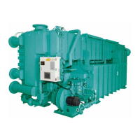
LD20188
Hot Insulation
Cold Insulation
FIGURE 7 - HOT/COLD INSULATION
4. The points that require hot insulation/cold insula-
tion are shown in Table 3 on page 29.
5. The casing of the absorber/condenser water cham-
ber does not require hot insulation/cold insulation.
If insulation is used, make it easily removable.
6. For the high temperature generator, install the in-
sulation in a way to permit removing the front,
sides, and rear separately. In addition, make a re-
movable part around the rear end for inspection of
the temperature relay and sensor.
 Loading...


