JOHNSON CONTROLS
52
FORM 155.32-ICOM1.EN.GB
ISSUE DATE: 10/13/2017
SECTION 4 - TECHNICAL DATA
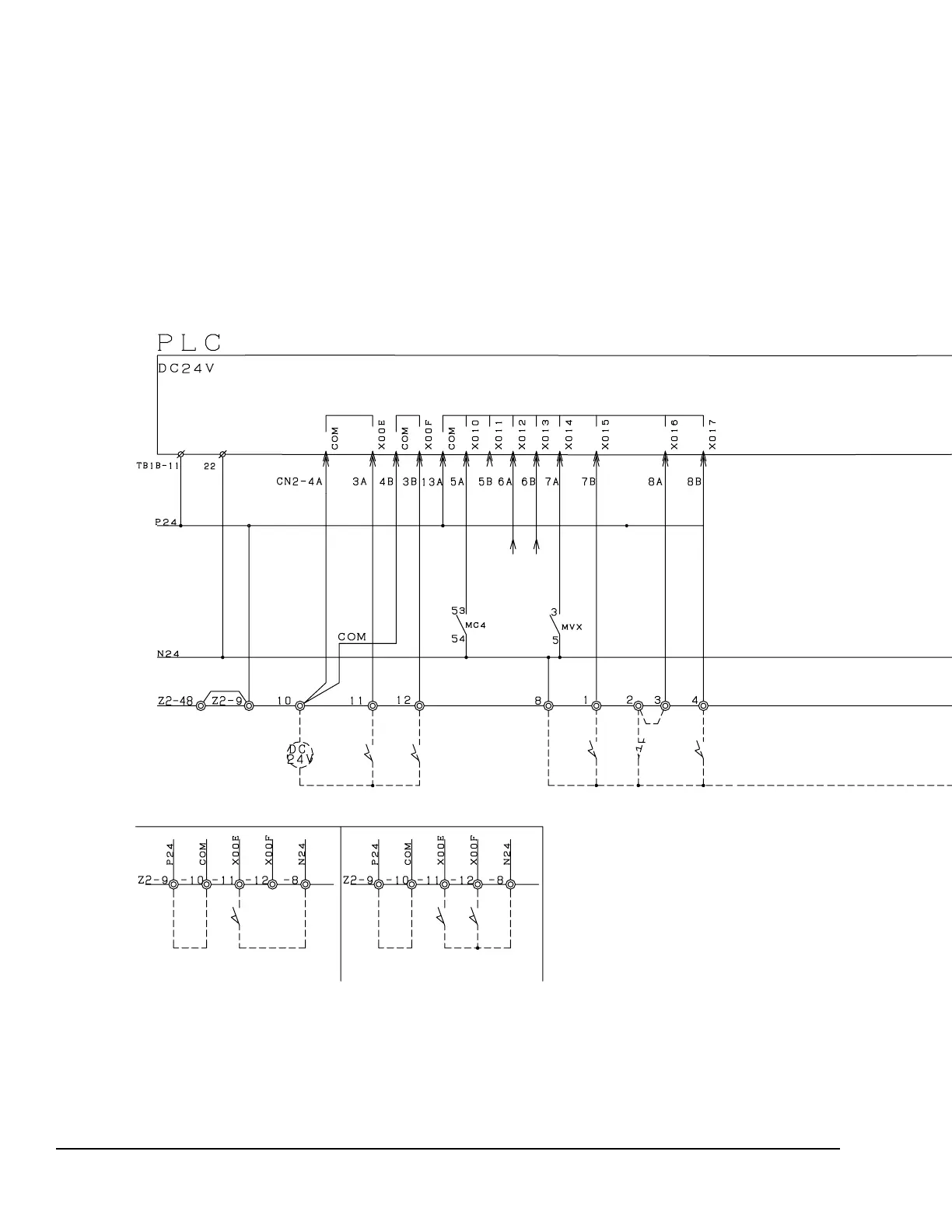
FIGURE 12 - PLC INPUT WIRING
LD20253
Input
Start Stop
Start Stop
Start
Remote Operation Signal
(DC24 V Pulse)
Remote Operation/Stop
Signal (Pulse)
Remote Operation/Stop
Signal (Level)
Burner Fan Operation Signal
Oil Pump Operation Signal (Oil Model)
Purge Pump
HT-GEN Solution Level
Combustion Signal
Chilled/Hot Water Pump Interlock
Constantly Monitoring Interlock
Cooling Water Pump Interlock
If a constantly monitoring cable is used, remove the jumper cable.
 Loading...


