JOHNSON CONTROLS
76
FORM 155.32-ICOM1.EN.GB
ISSUE DATE: 10/13/2017
SECTION 4 - TECHNICAL DATA
LD20184
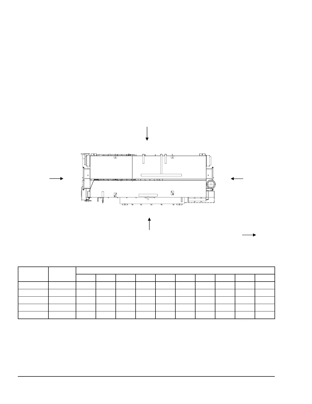
B Side
A Side
1
2
3
5
FIGURE 26 - SAMPLE SOUND TESTING
LOCATION* OVERALL
OCTAVE BAND
31.5 Hz 63 Hz 125 Hz 250 Hz 500 Hz 1 kHz 2 kHz 4 kHz 8 kHz 16 kHz
1 78/87 36/70 52/78 65/82 62/71 63/67 66/66 70/69 66/63 60/57 49/47
2 76/89 43/77 55/80 65/82 64/73 61/64 65/64 66/64 63/61 55/55 42/40
3 79/93 50/85 57/80 69/83 65/73 61/63 62/62 66/65 65/63 61/58 38/36
4 80/88 40/74 52/77 64/79 59/67 58/62 66/66 70/69 67/66 63/61 41/39
5 67/82 35/73 42/69 60/77 53/62 51/55 54/54 53/52 48/47 34/33 25/25
* Position of Measuring instrument
Height:1.5 m, Horizon:1.0 m (from chiller-heater surface)
NOTE: These data are reference value, as the chiller-heater unit was not covered with the thermal insulation materials and the water pipes
(for chilled/hot water, and cooling water) were temporary during the measurement.
Evaporator Side
Background
Noise
Generator Side
(Burner Side)
(Flue Gas
Duct Side)
 Loading...


