JOHNSON CONTROLS
75
SECTION 4 - TECHNICAL DATA
FORM 155.32-ICOM1.EN.GB
ISSUE DATE: 10/13/2017
4
LD20947
2
3
7
5
4
SG
1
RDB
SDA
SDB
RDA
9
6
CSA
ERB
CSB
ERA
8
100
Ω
(1/2W)
SDA
SDB
RDA
RDB
SG
100
Ω
(1/2W
FG
2
3
7
5
4
SG
1
RDB
SDA
SDB
RDA
9
6
CSA
ERB
CSB
ERA
8
Display
Shield
(Slave)
D-sub 9 pin (socket)
Signal name
External Device
(Master)
Your own cable
Pin
Signal name
Termination
resistance
Termination
resistance
Pin
Signal name
(Slave)
D-sub 9 pin (socket)
Shield
Shell
FG
Shell
FG
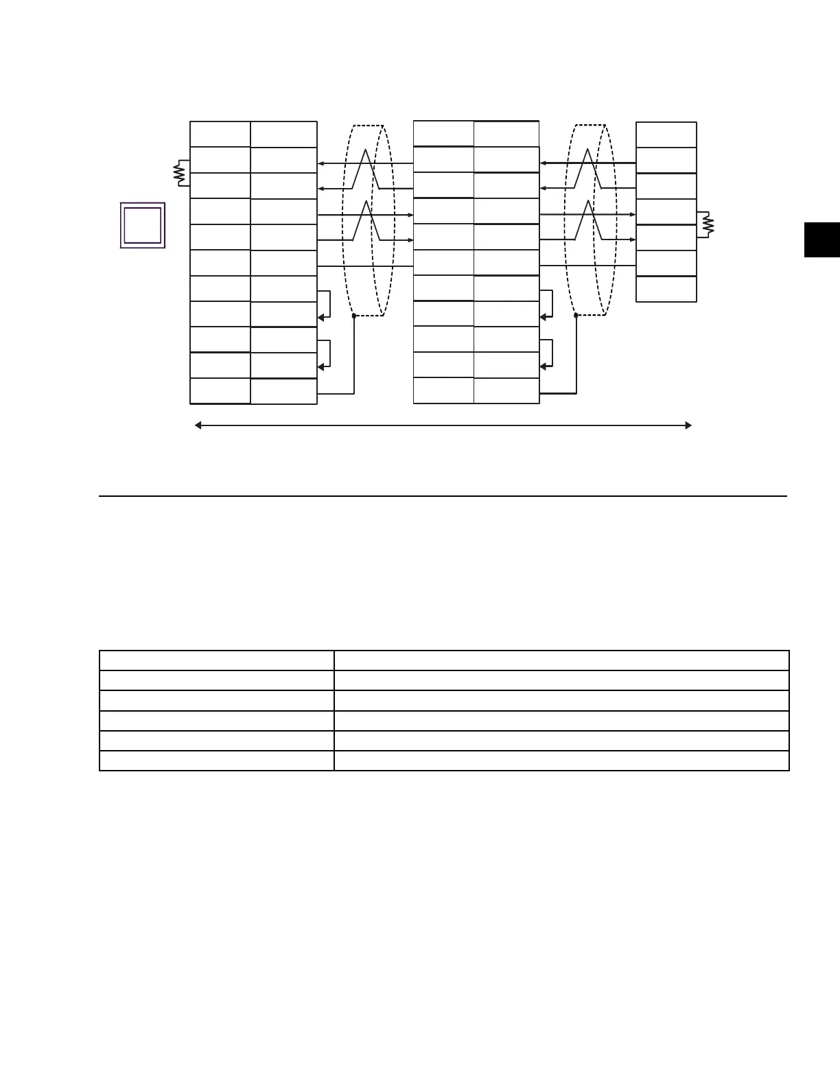
FIGURE 25 - 4-WIRE N:1 CONNECTION WITH USER-CREATED CABLE
The following table contains information about the
communication specifications needed for the Modbus
RTU. See Table 13 on page 65 for information about
the Read Command or Table 14 on page 69 for in-
formation about the Write Command.
Communication Protocol Modbus/RTU
Communication path type RS422/RS485 Data Length: 8 Bit Stop Bit: 1 Bit Parity: EVEN Speed: 9600 bps
Connector D-Sub 9pin
Function Code Read Coil Status:01 Read Holding Register:03
Device Digital Signal: Coil Analog Signal: Holding Register
Slave Equipment Address 1
TABLE 27 - COMMUNICATION SPECIFICATIONS
 Loading...


