JOHNSON CONTROLS
92
FORM 150.73-NM1
ISSUE DATE: 09/04/2020
SECTION 5 – TECHNICAL DATA
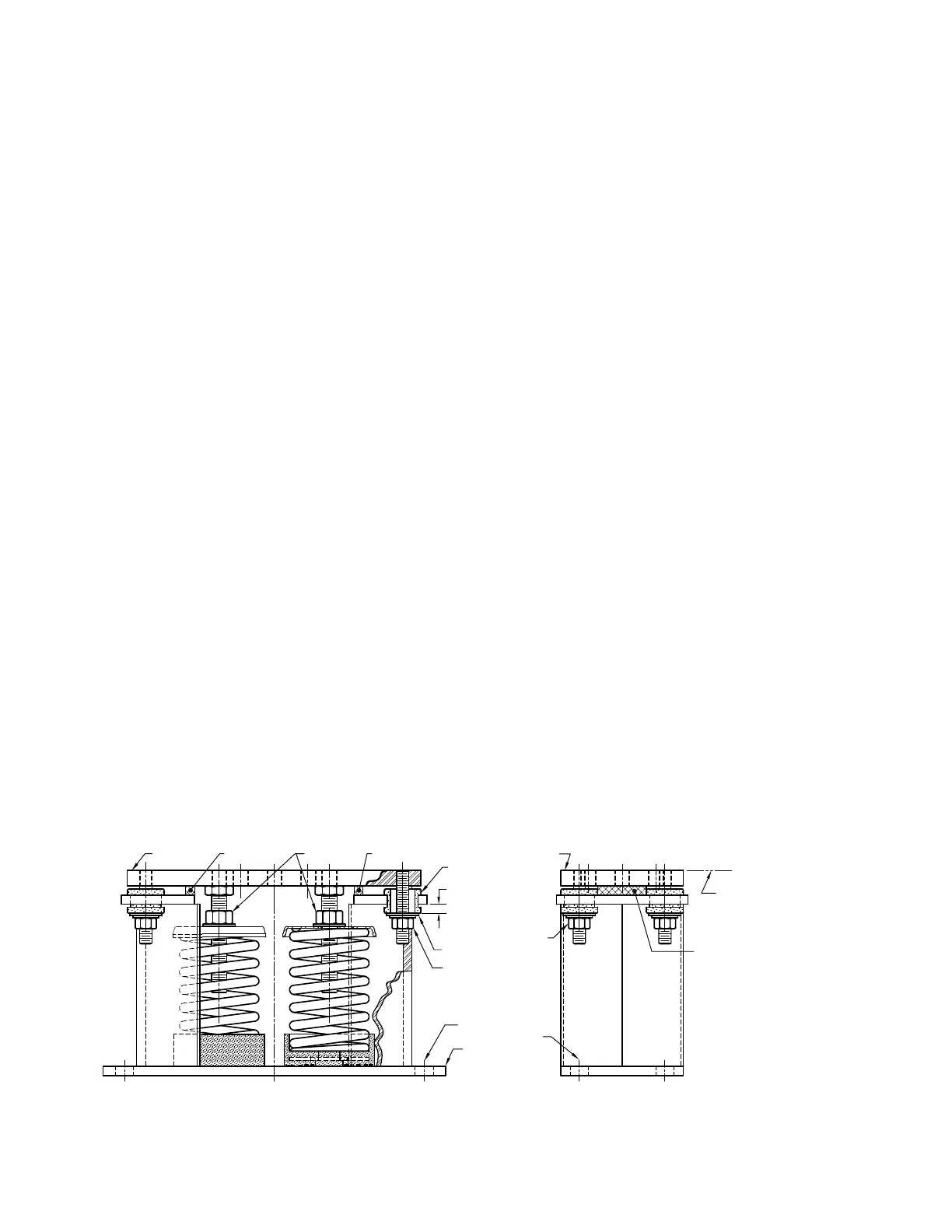
Seismic Isolator Installation and Adjustment
LD13763A
WASHER
("F")
("B")
GROMMET
("G")
("A")
("C")
("F")
("E")
("E")
("E")
1/4 - 3/8 GAP
C
L
C
L
("C")
EQUIPMENT
("A")
1. Read instructions in their entirety before begin-
ning installation.
2. Isolators are shipped fully assembled and are to be
positioned in accordance with the submittal draw-
ings or as otherwise recommended.
3. Set isolators on oor, housekeeping pad, or sub-
base, ensuring that all isolator centerlines match
the equipment mounting holes. The vmc group
recommends that the isolator base plates ("b") be
installed on a level surface. Shim or grout as re-
quired, leveling all isolator base plates to the same
elevation (1/4-in. maximum dierence can be tol-
erated).
4. Bolt or anchor all isolators to supporting struc-
ture utilizing base plate thru holes ("c") or weld
base plate to supporting structure with 3/8 llet
weld 2 in. long at 4 in. on center around entire
base plate or as engineered for specic load and
or eld conditions.
5. Isolators are shipped to the job site with (2) re-
movable spacer shims ("e") between the top plate
and the housing. These shims must be in place
when the equipment is positioned over the isola-
tors.
6. With all shims ("e") in place, position equipment
on top of plate ("a") of isolator. Bolt equipment
securely to top plate of isolator using a minimum
of (2) 5/8 unc a325 grade 5 sae bolt or weld equip-
ment or bracket to the top plate ("a") of isolator
with a minimum 3/8 llet welds 2 in. long at 3 in.
o.C. For a minimum total weld of 10 in. (All sides
of equipment or bracket resting on top plate ("a")
must be welded).
7. The adjustment process can only begin after the
equipment or machine is at its full operating
weight.
8. Back o each of the (4) limit stop lock nuts (“f”)
on isolators 1/2 in.
9. Adjust each isolator in sequence by turning spring
adjusting nuts (“g”) one full clockwise turn at a
time. Repeat this procedure on all isolators, one at
a time. Check the limit stop lock nuts (“f”) period-
ically to ensure that clearance between the washer
and rubber grommet is maintained. Stop adjust-
ment of isolator only when the top plate (“a”) has
risen just above the shim (“e”).
10. Remove all spacer shims (“e”).
11. Fine adjust isolators to level equipment.
12. Adjust all limit stop lock nuts (“f”) per isolator,
maintaining 1/4-to 3/8-in. gap. The limit stop nuts
must be kept at this gap to ensure uniform bolt
loading during uplift (as the case when equipment
is drained).
13. Installation is complete.