Motor and Drive System
Motor Stop Switch 30-15
30
6. Remove headlight inner fairing. See Headlight
Inner Fairing, page 60.3.
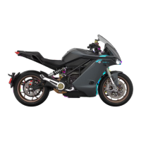
7. Cut cable tie securing the motor stop switch
harness, brake switch electrical harness,
throttle harness, and front wheel speed sensor
to hela bracket harness anchor.
Note: Replace cable tie during the installation
process.
8. Cut cable tie bundling the motor stop switch
harness, brake switch electrical harness, and
throttle harness.
Note: Replace cable tie during the installation
process.
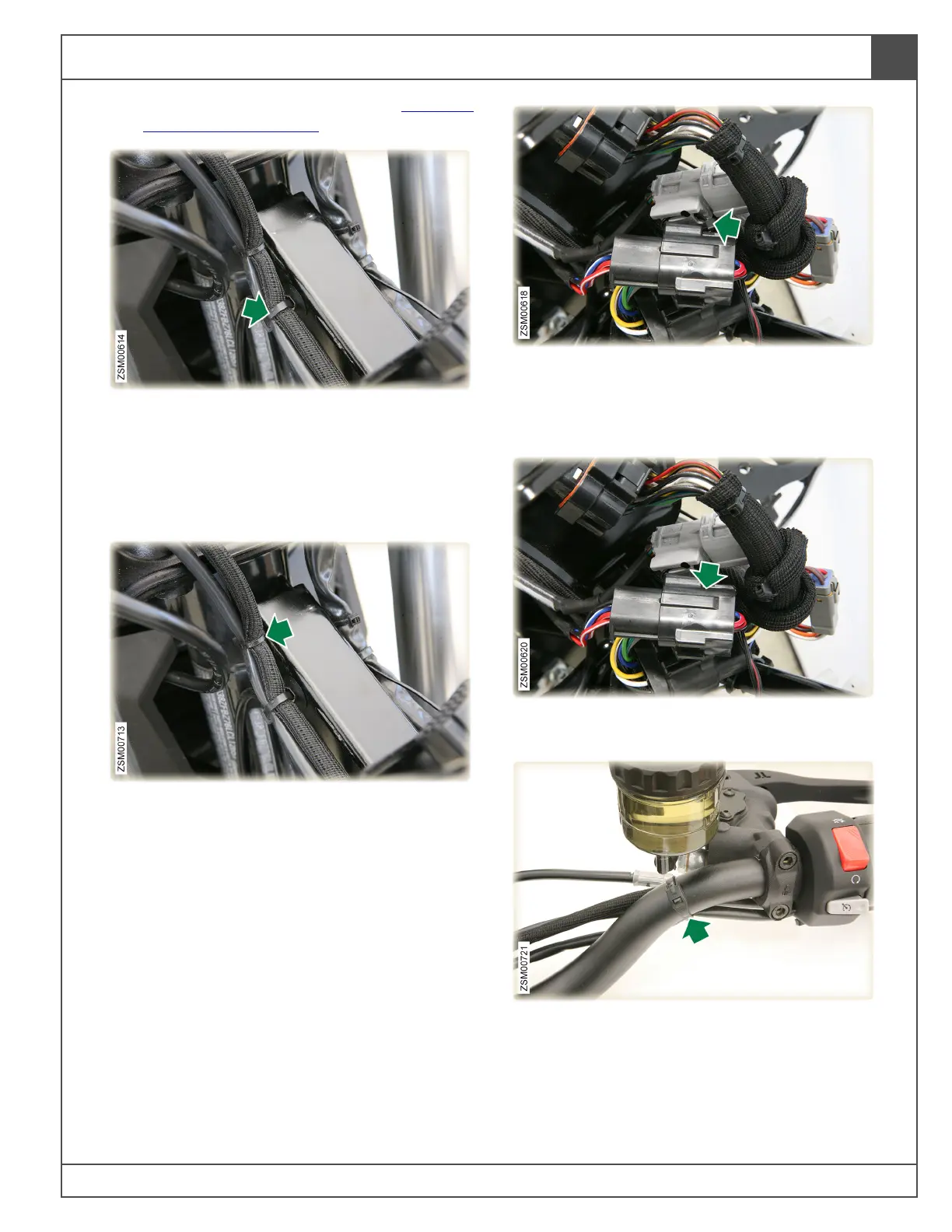
9. Cut cable tie securing motor stop switch
connector to the throttle connector.
Note: Replace cable tie during the installation
process.
10. Disconnect motor stop switch harness
connector.
11. Cut cable tie securing harness to the right side
of the handlebar.
Note: Replace cable tie during the installation
process.