Body
Body 60-15
60
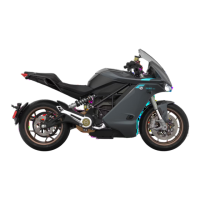
6. Cut cable tie securing right front turn signal
electrical harness to the right outer fairing arm.
Note: Replace cable tie during the installation
process.
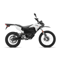
7. Disconnect left front turn signal harness
connectors.
Note: Take note of the wire insulation colors.
The turn signal wire colors match the colors of
the main wire harness.
Left turn signal wire colors: black and red.
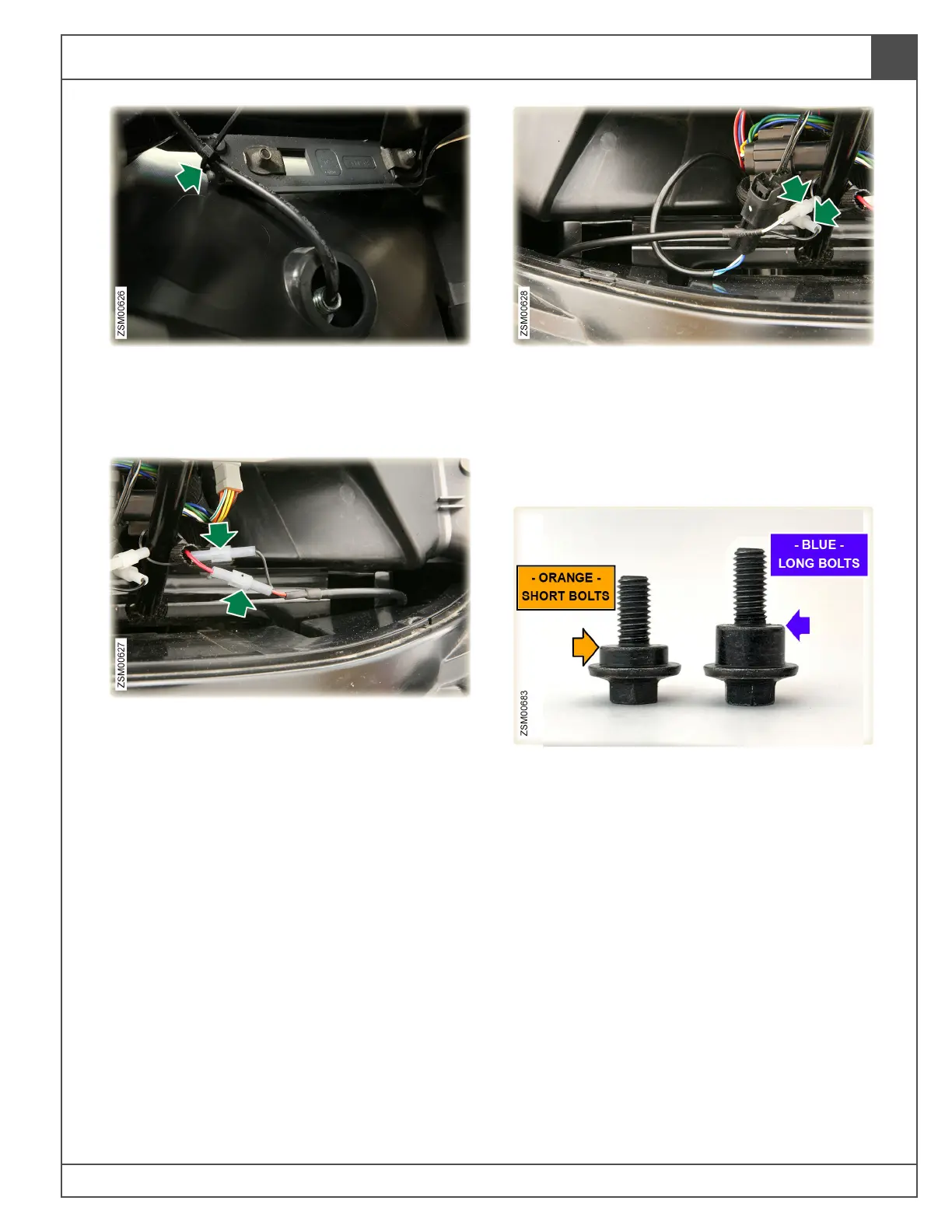
8. Disconnect right front turn signal harness
connectors.
Note: Take note of the wire insulation colors.
The turn signal wire colors match the colors of
the main wire harness.
Right turn signal wire colors: black and white.
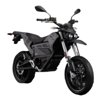
9. For the rest of this procedure, there will be
references to shouldered-bolts securing body
panels, that are 2 different lengths.
Short bolts: designated on photos with
orange arrows, used to attach a single body
panel layer.
Long bolts: designated on photos with blue
arrows, used to attach 2 layers of body panels.
Note: Non-shouldered body bolts designated
with green arrows are present in this
procedure.