70-38 Cellular Connectivity Module (CCM)
Electrical
70
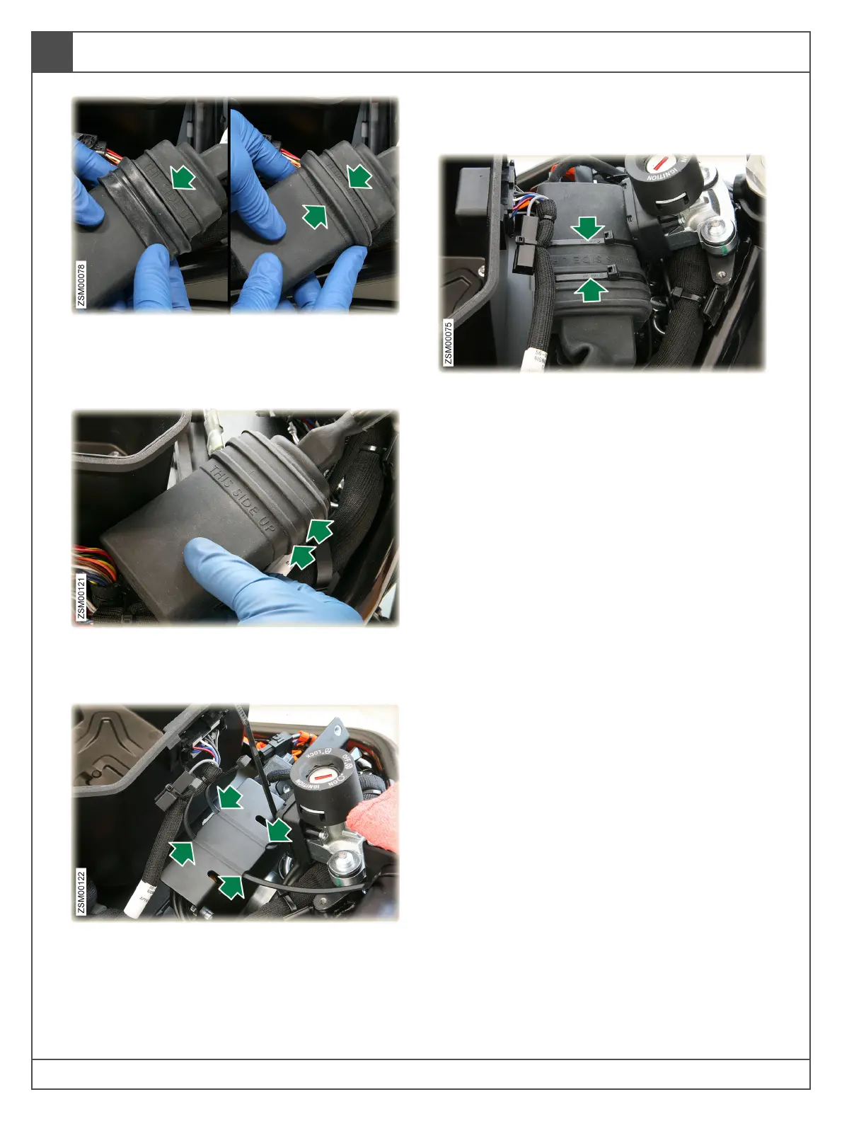
5. The CCM rubber end cap has the text “THIS
SIDE UP” printed on it. Confirm that the text on
the end cap is also facing the same as the
“THIS SIDE UP” on the rubber harness cover.
6. Confirm that both grooves in the CCM end cap
are interlocked with both of the ribs on the
harness boot cover.
7. Install new cable ties (x2) under the HCU
bracket. Line them up with the notches in the
bracket.
Note: Do not capture the wiring harness
located under the HCU bracket with the cable
ties.
8. Install the CCM back on the HCU bracket with
the text “THIS SIDE UP” text facing upward.
9. Follow the rest of the CCM Removal steps (3,
2, and 1) to complete the installation of the
CCM.
10. Once the CCM is physically installed, you
must email Zero Motorcycles Customer
Service department to complete the
installation procedure and activate the
module. Zero Motorcycles will need the VIN of
the motorcycle and additional information to
complete the installation.
• North America:
support@zeromotorcycles.com
• Zero Motorcycles Europe:
service.eu@zeromotorcycles.com