20-16 Power Pack
Power Pack
20
Removal
1. PERFORM LOCKOUT PROCEDURE: See
Lockout Procedure, page 10.1.
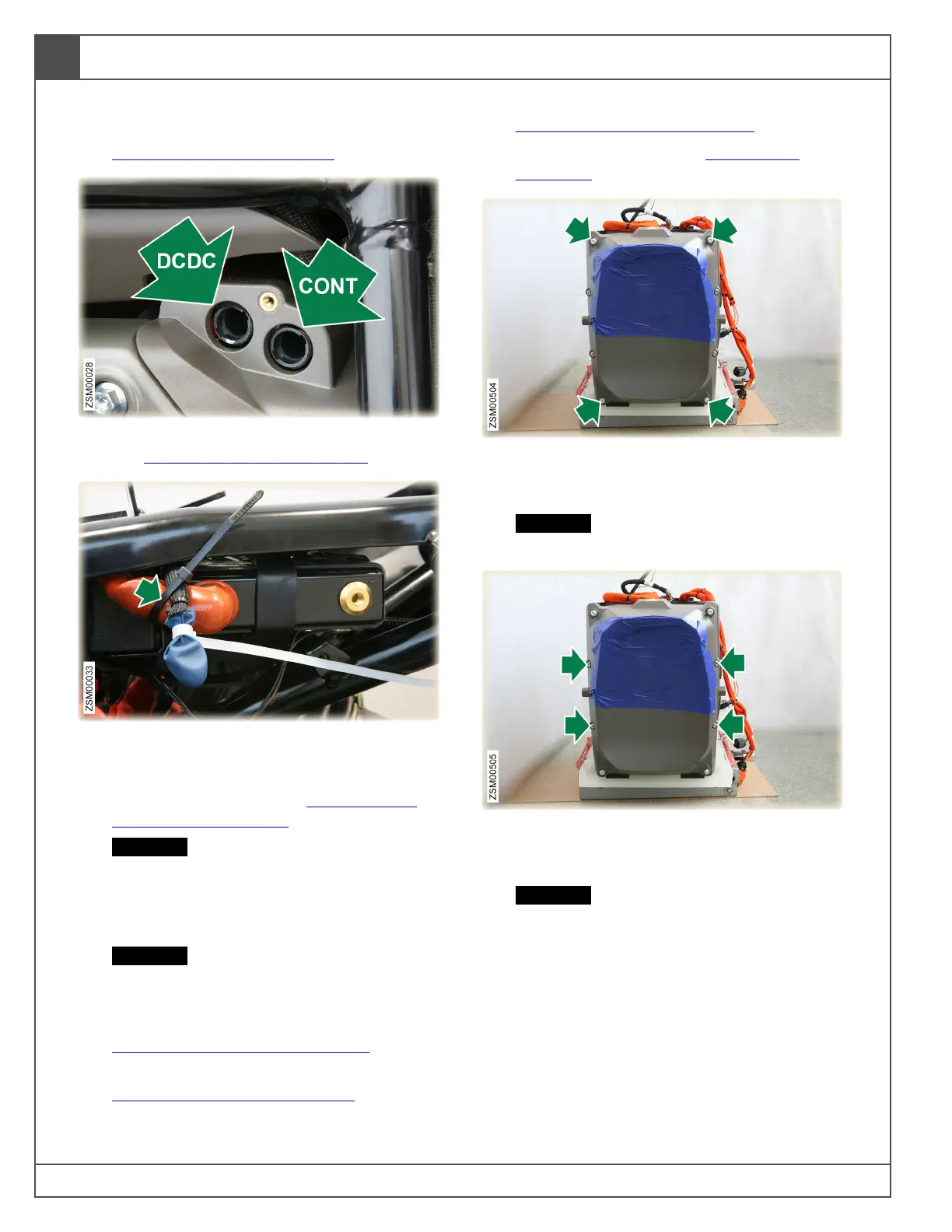
2. Remove high voltage DCDC and CONT fuses.
See High Voltage Fuses, page 70.1.
3. Unbolt the negative battery terminal eyelet.
Cover eyelet with insulating material. Use
cable tie to secure negative battery wire to the
positive battery cable. See 12 Volt Battery
(Disconnect), page 70.3.
CAUTION: Cover/protect battery terminal
eyelet to reduce the risk of accidentally
contacting the negative battery terminal,
which can inadvertently power up the
12 volt system and damage components.
CAUTION: Secure battery terminal wire to
reduce the risk of arcing and damaging
electrical components.
4. Remove headlight upper fairing. See
Headlight Upper Fairing, page 60.2.
5. Remove left and right outer side fairings. See
Side Fairings (Outer), page 60.14.
6. Remove left and right inner side fairings. See
Side Fairings (Inner), page 60.19.
7. Remove power pack. See Power Pack,
page 20.1.
8. Remove bolts (x4) securing the four corners of
the front cover to the power pack. Bolt:
M5x30. Tool: T20. Torque: 18 in-lb (2.3 Nm).
CAUTION: Be very careful with the bolt
lengths during installation.
9. Remove bolts (x4) securing center of the front
cover to the power pack. Bolt: M5x10. Tool:
T20. Torque: 18 in-lb (2.3 Nm).
CAUTION: Be very careful with the bolt
lengths during installation.