I/O
Ports
9.6
PORT
HANDSHAKE
When
Ports
0,
1,
or
2
are
configured
for
hand-
shake
operation,
a
pair
of
lines
from
Port
3
is
used
for
handshake
controls
for
each
port.
The
handshake
controls
are
interlocked
to
properly
time asynchronous
data
transfers
between
t.he
Z8
and
its
peripheral.
One
control
line
(DAV
n
) func-
tions
as
a
strobe
from
the
sender
to
indicate
to
the
receiver
that
data
is
available.
The
second
control
line
(RDY
n
)
acknowledges
receipt
of
the
sender's
data,
and
indicates
when
the
receiver
is
ready
to
accept
another
data
transfer.
In
the
input
mode,
data
is
latched
into
the
port's
input
register
by
the
first
DAV
signal,
and
is
protected
from
being
overwritten
if
additional
pulses
occur
on
the
DAV
line.
This
overwrite
pro-
tection
is
maintained
until
the
port
data
is
read.
In
the
output
mode,
data
written
to
the
port
is
not
protected
and
can
be
overwritten
by
the
Z8
during
the
handshake sequence.
To
avoid
losing
data,
the
software
must not
overwrite
the
port
until
the
corresponding
interrupt
request
indicates
that
the
external
device has
latched
the
data.
The
software
can always read
Port
3
output
and
input
handshake
lines,
but
cannot
write
to
the
output
handshake
lines.
DAV
(INPUT TO
Z8)
2
RDY
(OUTPUT FROM
Z8)
---+-.,.
DATA
ON
PORT
(INPUT TO
Z8)
Following
is
the
recommended
setup
sequence
when
configuring
a
port
for
handshake
operation
for
the
first
time
after
a
reset:
•
Load
P01
M
or
P2M
to
configure
the
port
for
input/output.
•
Load
P3
to
set
the
Output Handshake
bit
to
a
logic
1.
•
Load
P3M
to
se
lect
the
Handshake
mode
for
the
port.
Once
a
data
transfer
begins,
the
configuration
of
the handshake
lines
should not
be
changed
until
handshake
is
completed.
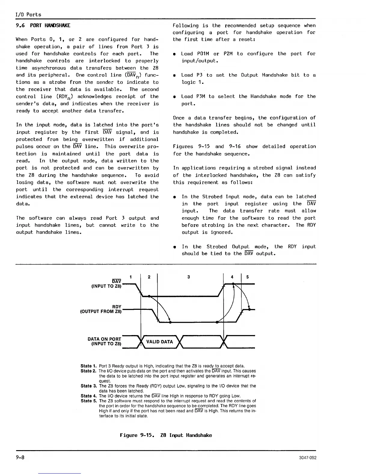
Figures
9-15
and
9-16
show
detailed
operation
for
the
handshake sequence.
In
applications
requiring
a
strobed
signal
instead
of
the
interlocked
handshake,
the
Z8
can
satisfy
this
requirement as
follows:
• In the Strobed Input
mode,
data
can
be
latched
in
the
port
input
register
using
the
DAV
input.
The
data
transfer
rate
must allow
enough time
for
the
software
to
read
the
port
before
strobing
in
the
next
character.
The
RDY
output
is
ignored.
•
In
the
Strobed
Output
mode,
the
RDY
input
should be
tied
to
the
DAV
output.
3 4
State
1. Port 3 Ready output is High, indicating that the
Z8
is ready to accept data.
State
2. The
1/0
device puts data
on
the port and then activates the
r:5AV
input. This causes
the data to
be
latched into the port input register and generates an interrupt re-
quest.
State
3.
The
Z8
forces the Ready (ROY) output Low, signaling to the
1/0
device that the
data has been
latched.
State
4. The
1/0
device returns the
OAV
line High
in
response to
ROY
going Low.
State
5. The
Z8
software must respond to the interrupt request and read the contents of
the port
in
order for the handshake sequence to
be
completed. The RDY line goes
High if and
only
if
the port has not been read and
DAIJ
is
High. This returns the in-
terface to its initial state.
Figure
9-15.
Z8
Input
Handshake
9-8
3047-092

 Loading...
