~xternal
Interface
lZB6Bl,ZB6B2)
PDo-P07' P2o-P27, P30-P37. I/O
Port
lines
(inputs/outputs,
TTL-compatible). These
24
I/O
lines
are
divided
into
3
8-bit
I/O
ports
that
can
be
configured
under program cont
rol
for
I/O
or
memory
interface.
Individual
lines
of
a
port
are
denoted
by
the
second
digit
of
the
port
number.
For example,
P3
0
refers
to
bit
0
of
Port
3.
RESET.
Reset
(input,
active
low,
pin
6).
RESET
initializes
the
Z8681/82.
When
RESET
is
deactivated,
program
execution
begins
from
external
program
location
%C
for
the
Z8681
and
location
%812
for
the
Z8682.
If
held
Low,
RESET
acts
as
a
register
file
protect
during power-down
and power-up sequences.
XTAl1,
XTAl2.
Crystal
1,
Crystal
2
(oscillator
input
and
output,
pins
3 and
2).
These
pins
connect a
parallel
resonant
crystal
or
an
external
source
to
the on-board
clock
osci
llator
and
buf-
fer.
7.3
CONFIGURING
PORT
0
The
minimum
bus
configuration
uses
Port
1
as
a
multiplexed
Address/Data
port
(ADO-AD7)
allowing
access
to
256
bytes
of
memory.
In
this
configura-
tion,
the
eight
low
order
address
bits
(AO-A7)
are
multiplexed
with
the
data
(DO-D7).
Port
0 can be programmed
to
provide
either
four
additional
address
lines
(A
8
-A11) which
increases
the
addressable
memory
to
4K
bytes,
or
eight
additional
address
lines
(A
8
-A
1
5) which
increases
the
addressable
memory
to
64K
bytes
for
the
Z8681
and
62K
bytes
for
the
Z8682. Refer
to
Chapter 3,
Figures
3-5 and
3-6,
for
the
memory
maps.
In
the
Z8681
,
Port
0
lines
intended
for
use
as
address
lines
are
automatically
configured
as
inputs
after
a
Reset.
These
lines
therefore
float
and
their
logic
state
remains
unknown
until
an
initialization
routine
configures
Port
O.
In
the
Z8682,
Port
0
lines
are
configured
as
address
lines
A
8
-A
15
following a
Reset.
7.3.1
lB6B1
Initialization
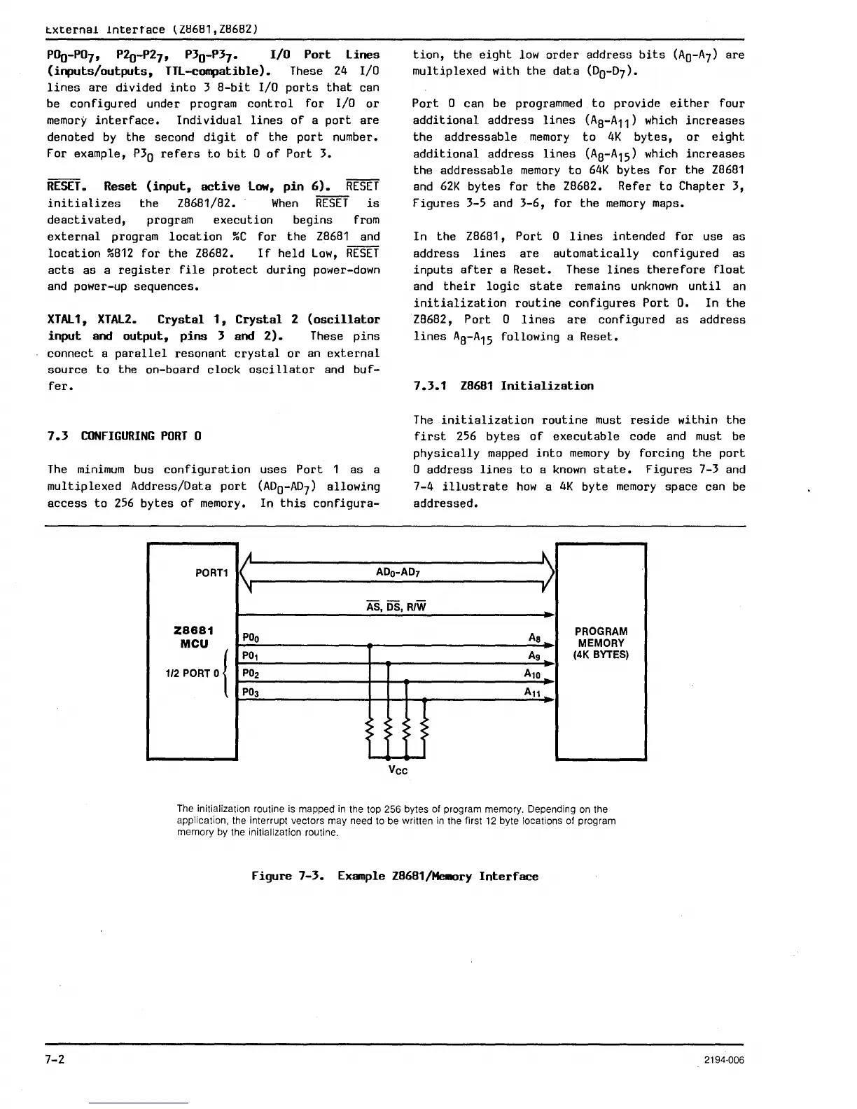
The
initialization
routine
must
reside
within
the
first
256
bytes
of
executable
code and must be
physically
mapped
into
memory
by
forcing
the
port
o
address
lines
to
a
known
state.
Figures
7-3 and
7-4
illustrate
how
a
4K
byte
memory
space can
be
addressed.
PORn
<
ADo-ADT
>
As,
OS,
RlW
Z8681
POo
As
PROGRAM
MCU
MEMORY
112
PORT
o{
POl
Ag
(4K BYTES)
P02
Al0
P03
An
<C
Vee
The initialization routine is mapped
in
the top 256 bytes of program memory. Depending
on
the
application, the interrupt vectors may need to be written
in
the first
12
byte locations of program
memory by the
initialization routine.
Figure
7-3.
Example lB6B1/He.ary
Interface
7-2 2194·006

 Loading...
