Product Manual - ZMORPH i500 back to table of content
>>
41
5. After machine nish the print you can now adjust the osets
using the print result.
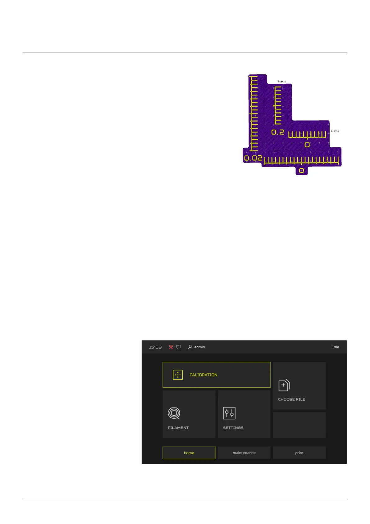
You need to nd the matching lines. At rst match the lines in
0.02 range (the external scale), each line represent -+ 0.02mm.
For example if you nd that in X-axis the matching line is the
3rd line from “0” to the right it means that you need to add the
0.06mm to X oset value, if it’s the 3rd line to the left it means
you need to substract 0.06mm from X oset value. Similar for
the Y-axis.
6. If you don’t nd the right value on the external scale, look for it on the inner scale (0.2 range).
7. Once you set the range you need to print the calibration parttern again
8. If all lines are matching at “0” the XY oset is calibrated.
Maintenance
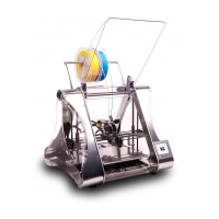
1. From main menu go to the
CALIBRATION menu.
10.4.3 Z Oset Calibration
Z oset calibration allows to set the oset between nozzles in Z-axis.
To perform the Z axis calibration: