9
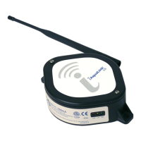
2.2 I Installing the temperature sensor
• The water temperature sensor displays the water temperature value on the appliance screen and manages
chlorinaon according to the temperature. The sensor must measure the temperature of the water
upstream of any possible heang system.
• The sensor is designed to be mounted on rigid Ø50 mm, Ø63 mm or Ø1 ½’’ PVC pipes. Do not install on any
other type of pipe.
• Install the sensor either between the lter pump and the lter, or between the lter and any other
downstream equipment, see “2.1 I Installing the cell”:
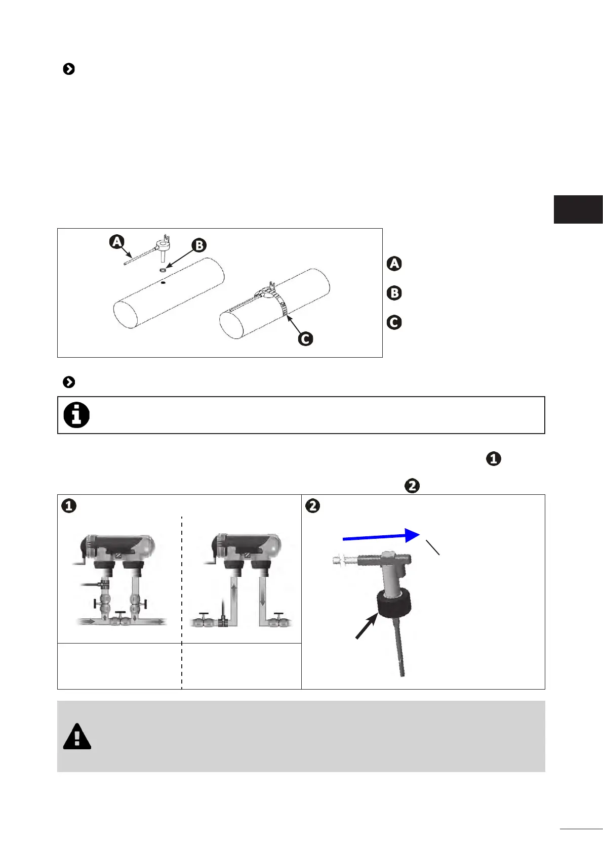
- Drill a hole in the pipe using a Ø9 mm (max. Ø10 mm) drill bit, then deburr the hole,
- Install the O-ring provided on the sensor body,
- Secure the sensor using the stainless-steel clamping collar provided. Do not use excess strength.
: Sensor
: O-ring
: Stainless steel clamping collar
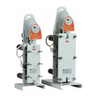
2.3 I Installing the ow switch (chlorinator only without pH Link or Dual Link modules)
In cases where a pH Link or Dual Link module is used, the ow switch will be installed on the POD
Kit, see “3.3 I Installing the ow switch on the POD kit”
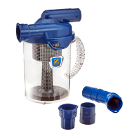
• The ow switch and its 50 mm diameter xture collar supplied as standard (63 mm diameter available
as a spare part) must be installed immediately before the cell and aer any valves present ( ). Use the
threaded adapter and the Teon tape provided to install the ow switch on its xture collar.
• Screw the ow switch using using the clamping nut only (screw by hand!) ( ).
Clamping
nut
Direcon of water
ow
Installaon on a by-pass In-line installaon
• Failure to comply with these instrucons could lead to the destrucon of the cell! The
manufacturer cannot be held liable in this case.
• The ow switch has a direcon for installaon (arrow indicated on it showing the ow
direcon for the water). Make sure that it is correctly placed on its xture collar so that it
stops the appliance's producon when ltering is stopped.
EN