8
❷ Installing the chlorinator
2.1 I Installing the cell
• The cell must be installed on the piping aer the ltraon system, aer any measurement sensors, and
aer any heang system.
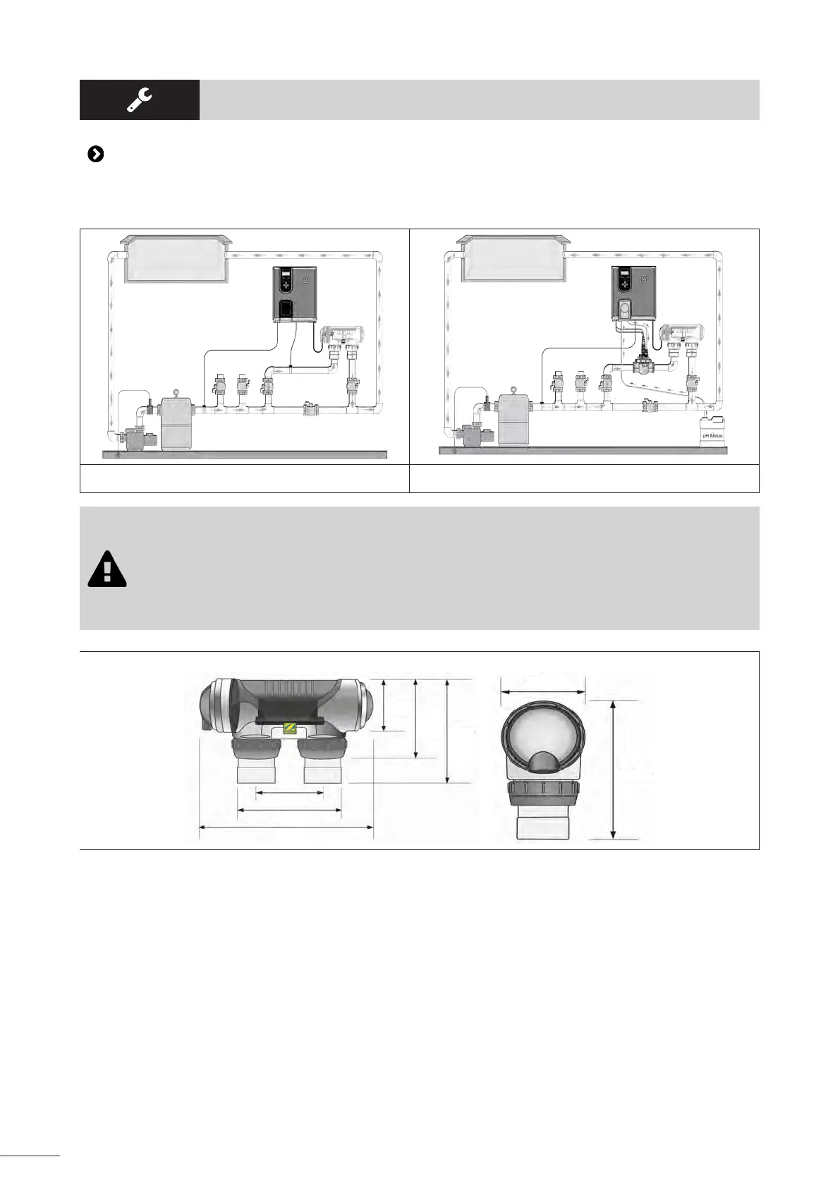
Installing the chlorinator only Installing the chlorinator + oponal module
• The cell must always be the last element placed on the pool return pipe (see diagram).
• It is always recommended to install the cell on a by-pass. This assembly is MANDATORY if the
ow is in excess of 18 m³/hour to avoid head loss.
• If you installed the cell on a by-pass, it is recommended to t a check valve downstream from
the cell instead of a manual valve, to avoid any risk of incorrect conguraon which could
result in poor circulaon inside the cell.
12.5 cm
21.5 cm
32 cm
11 cm
15.5
cm
21.5
cm
11 cm
21.5 cm
• Make sure that the cell is placed HORIZONTALLY. The water should ow from the electric connecons
towards the opposite side.
• Use the screw-on ngs to x the cell to the pipes.
• For Ø63 mm pipes, glue them directly to the screw-on ngs. For Ø50 mm pipes, use glue-on PVC adapters
of the corresponding diameter (grey models; the white models are for 1 ½’’ UK pipes).
• Connect the cell power cord following the wire colour codes (red, black and blue connectors) and then ret
the protecve cap. The two red wires can be connected to one or the other red terminals on the electrode.