IES4005M User’s Guide 59
CHAPTER 8
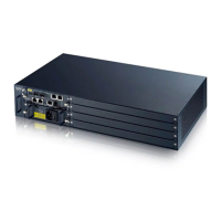
Hardware Installation
This chapter describes how to install and connect the IES and line cards.
8.1 General Installation Instructions
Perform the installation as follows:
• Make sure the IES’s power switches are in the OFF position.
• Install the main chassis as detailed in this chapter. Make sure you connect the frame grounds
before you make any other connections.
• If line cards are not already installed, follow the procedure in the next section to install them.
• Refer to Section 7.7 on page 54 for instructions on making connections with Telco-64 connectors.
• Refer to Section 3.2.3 on page 24 for instructions on making alarm connections.
• Refer to Chapter 5 on page 39 for instructions on making power connections and turning on the
IES.
8.2 Main Chassis Installation
This section explains how to install the main chassis on a rack.
8.2.1 Rack-mounted Installation Requirements
Make sure the rack will safely support the combined weight of all the equipment it contains.
• Use a #2 Phillips screwdriver to install the screws.
• Refer to Chapter 29 on page 221 for the gauge of wire to use for the frame ground connections.
• Refer to Chapter 29 on page 221 for the IES’s dimensions, weights and power consumption.
Failure to use the proper screws may damage the unit.
8.2.2 Mounting the Main Chassis on a Rack
Make sure that nothing obstructs the airflow of the main chassis.
• If you are facing the IES front panel, the fan tray located in the left of the IES chassis houses
three fans to blow air for ventilation. Cool air enters the chassis through intake vents on the left
side panel and flows towards the right side where it exits.
 Loading...