140 CHAPTER 14: MSTP CONFIGURATION
non-root-bridge device has one and only one root port. The root bridge has no
root port.
3 Designated bridge and designated port
Refer to Table 95 for the description of designated bridge and designated port.
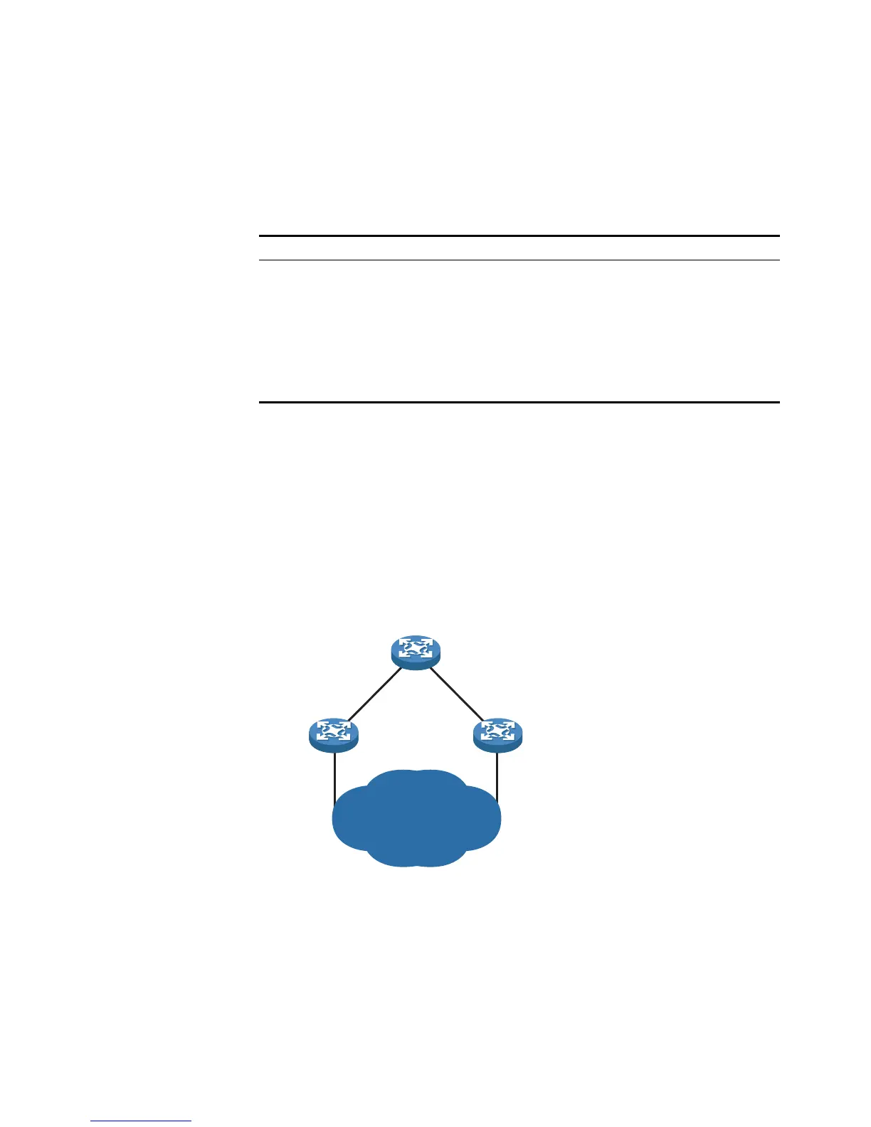
Figure 46 shows designated bridges and designated ports. In the figure, AP1 and
AP2, BP1 and BP2, and CP1 and CP2 are ports on Device A, Device B, and Device
C respectively.
■ If Device A forwards BPDUs to Device B through AP1, the designated bridge for
Device B is Device A, and the designated port is the port AP1 on Device A.
■ Two devices are connected to the LAN: Device B and Device C. If Device B
forwards BPDUs to the LAN, the designated bridge for the LAN is Device B, and
the designated port is the port BP2 on Device B.
Figure 46 A schematic diagram of designated bridges and designated ports
n
All the ports on the root bridge are designated ports.
4 Path cost
Path cost is a value used for measuring link capacity. By comparing the path costs
of different links, STP selects the most robust links and blocks the other links to
prune the network into a tree.
Tabl e 95 Designated bridge and designated port
Classification Designated bridge Designated port
For a device A designated bridge is a
device that is directly
connected to a switch and is
responsible for forwarding
BPDUs to this switch.
The port through which the
designated bridge forwards
BPDUs to this device
For a LAN A designated bridge is a
device responsible for
forwarding BPDUs to this LAN
segment.
The port through which the
designated bridge forwards
BPDUs to this LAN segment
LAN
AP1 AP2
Device A
Device B Device C
BP1
BP2
CP1
CP2