334 CHAPTER 30: CLUSTER
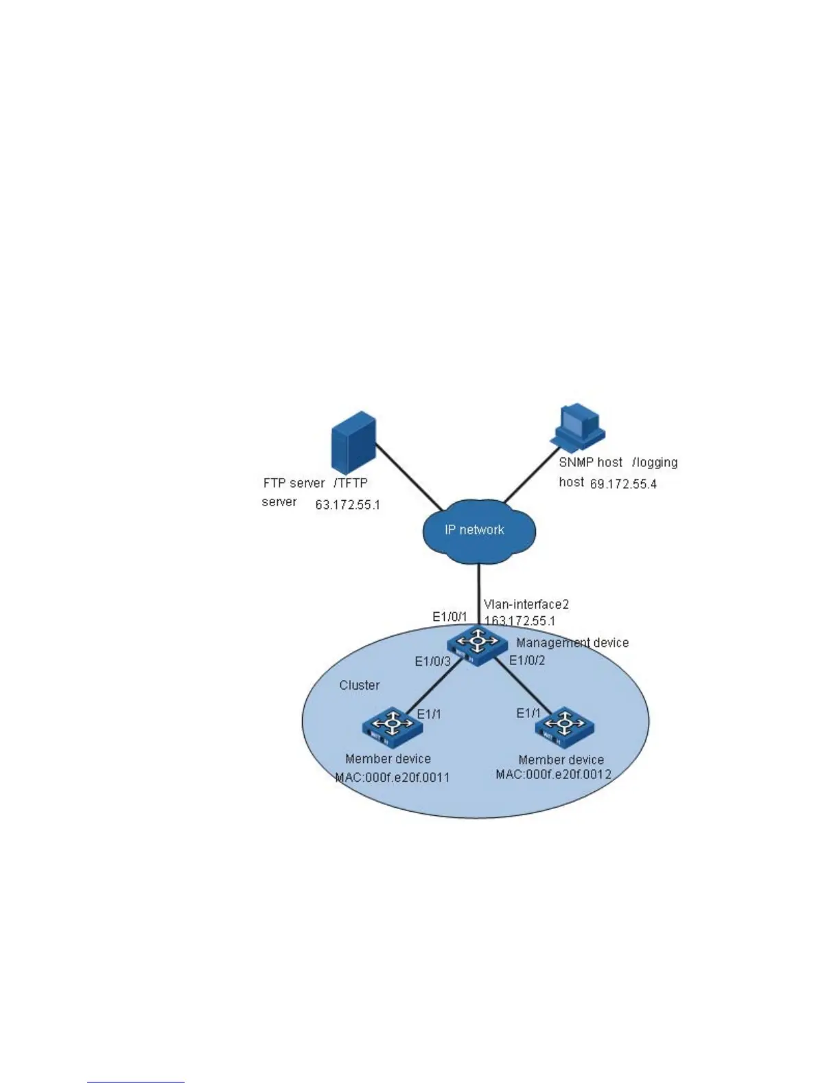
Serving as the management device, the Switch 4210 manages the two member
devices. The configuration for the cluster is as follows:
■ The two member devices connect to the management device through Ethernet
1/0/2 and Ethernet 1/0/3.
■ The management device connects to the Internet through Ethernet 1/0/1.
■ Ethernet 1/0/1 belongs to VLAN 2, whose interface IP address is 163.172.55.1.
■ All the devices in the cluster share the same FTP server and TFTP server.
■ The FTP server and TFTP server use the same IP address: 63.172.55.1.
■ The NMS and logging host use the same IP address: 69.172.55.4.
Network diagram
Figure 102 Network diagram for Switch Clustering cluster configuration
Configuration procedure
1 Configure the member devices (taking one member as an example)
# Enable NDP globally and on Ethernet1/1.
<4210> system-view
[4210] ndp enable
[4210] interface Ethernet 1/1
[4210-Ethernet1/1] ndp enable
[4210-Ethernet1/1] quit
# Enable NTDP globally and on Ethernet1/1.