126 CHAPTER 6: IP ROUTING PROTOCOL OPERATION
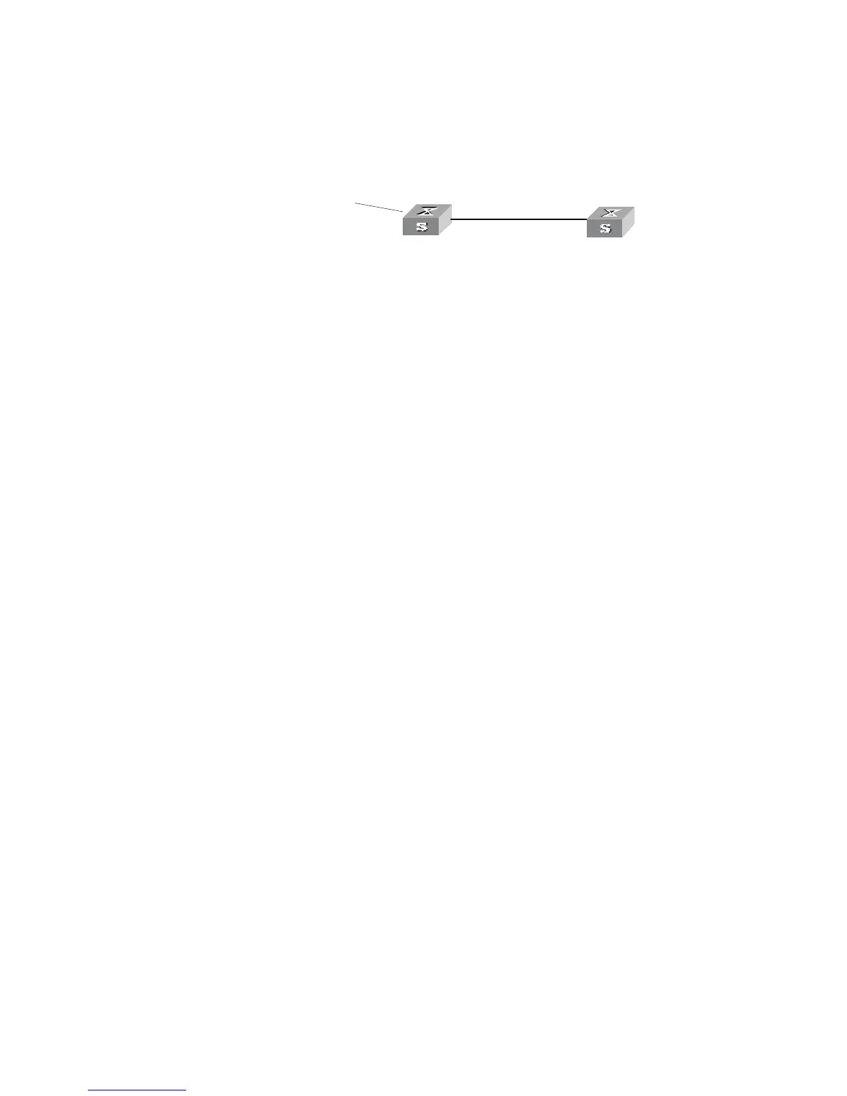
Networking diagram
Figure 34 Filtering the received routing information
Configuration procedure
1 Configure Switch A:
a Configure the IP address of VLAN interface.
[Switch A]interface vlan-interface 100
[Switch A-Vlan-interface100]ip address 10.0.0.1 255.0.0.0
[Switch A]interface vlan-interface 200
[Switch A-Vlan-interface200]ip address 12.0.0.1 255.0.0.0
b Configure three static routes.
[Switch A]ip route-static 20.0.0.1 255.0.0.0 12.0.0.2
[Switch A]ip route-static 30.0.0.1 255.0.0.0 12.0.0.2
[Switch A]ip route-static 40.0.0.1 255.0.0.0 12.0.0.2
c Enable RIP protocol and specifies the number of the area to which the interface
belongs.
[Switch A]router id 1.1.1.1
[Switch A]rip
[Switch A-rip-1]area 0
[Switch A-rip-1-area-0.0.0.0]network 10.0.0.0 0.255.255.255
d Import the static routes
[Switch A-rip-1]import-route static
2 Configure Switch B:
a Configure the IP address of VLAN interface.
[Switch B]interface vlan-interface 100
[Switch B-Vlan-interface100]ip address 10.0.0.2 255.0.0.0
b Configure the access control list.
[Switch B]acl number 2000
[Switch B-acl-basic-2000]rule deny source 30.0.0.0 0.255.255.255
[Switch B-acl-basic-2000]rule permit source any
c Enable RIP protocol and specifies the number of the area to which the interface
belongs.
[Switch B]router id 2.2.2.2
[Switch B]rip
[Switch B-rip-1]area 0
[Switch B-rip-1-area-0.0.0.0]network 10.0.0.0 0.255.255.255
d Configure RIP to filter the external routes received.
[Switch B-rip-1]filter-policy 2000 import
area 0
sta tic 20.0.0 .0/8
30.0.0.0 /8
40.0.0.0 /8
R o u ter ID :1.1.1.1
10.0 .0.2/8
Swi tch A
Swit ch B
Vlan- interface200
12.0 .0.1/8
Router ID:2.2.2.2
Vlan-in terface10 0
10.0.0 .1/8 Vlan-i nterface1 00
 Loading...