60 CHAPTER 3: VLAN OPERATION
Networking Diagram
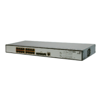
Figure 14 VLAN Configuration Example 1
Configuration Procedure
1 Create VLAN 2 and enter its view.
[4500]vlan 2
2 Add Ethernet1/0/1 and Ethernet1/0/2 to VLAN2.
[4500-vlan2]port ethernet1/0/1 to ethernet1/0/2
3 Create VLAN 3 and enter its view.
[4500-vlan2]vlan 3
4 Add Ethernet1/0/3 and Ethernet1/0/4 to VLAN3.
[4500-vlan3]port ethernet1/0/3 to ethernet1/0/4
VLAN Configuration
Example Two
Networking Requirements
Configure an IP address on a VLAN interface.
Networking Diagram
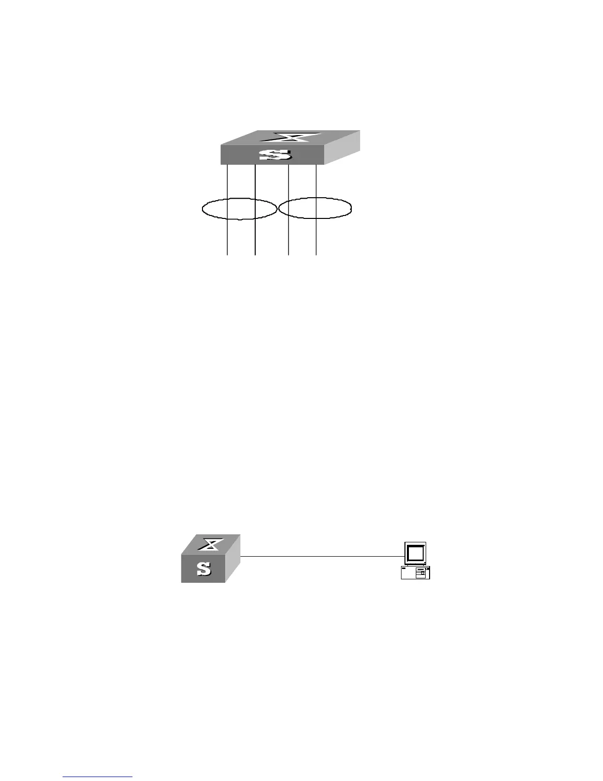
Figure 15 VLAN Configuration Example 2
Configuration Procedure
1 If the VLAN does not currently exist, then create it. This example uses VLAN ID 3.
[4500]vlan 3
[4500-vlan3]quit
2 Enter the VLAN interface view:
[4500]interface vlan-interface 3
3 Provide the IP address and subnet mask:
[4500-Vlan-interface3]ip address 192.168.1.5 255.255.255
[4500-Vlan-interface3]quit
VLAN3
Switch
E1/0/3
E1/0/2
VLAN2
VLAN3
E1/0/4
E1/0/1
Switch
VLAN3
Switch
E1/0/3
E1/0/2
VLAN2
VLAN3
E1/0/4
E1/0/1
Switch
VLAN 3
192.168.1.5 255.255.255.0
Switch
VLAN 3
192.168.1.5 255.255.255.0
Switch
 Loading...