Network
diagram
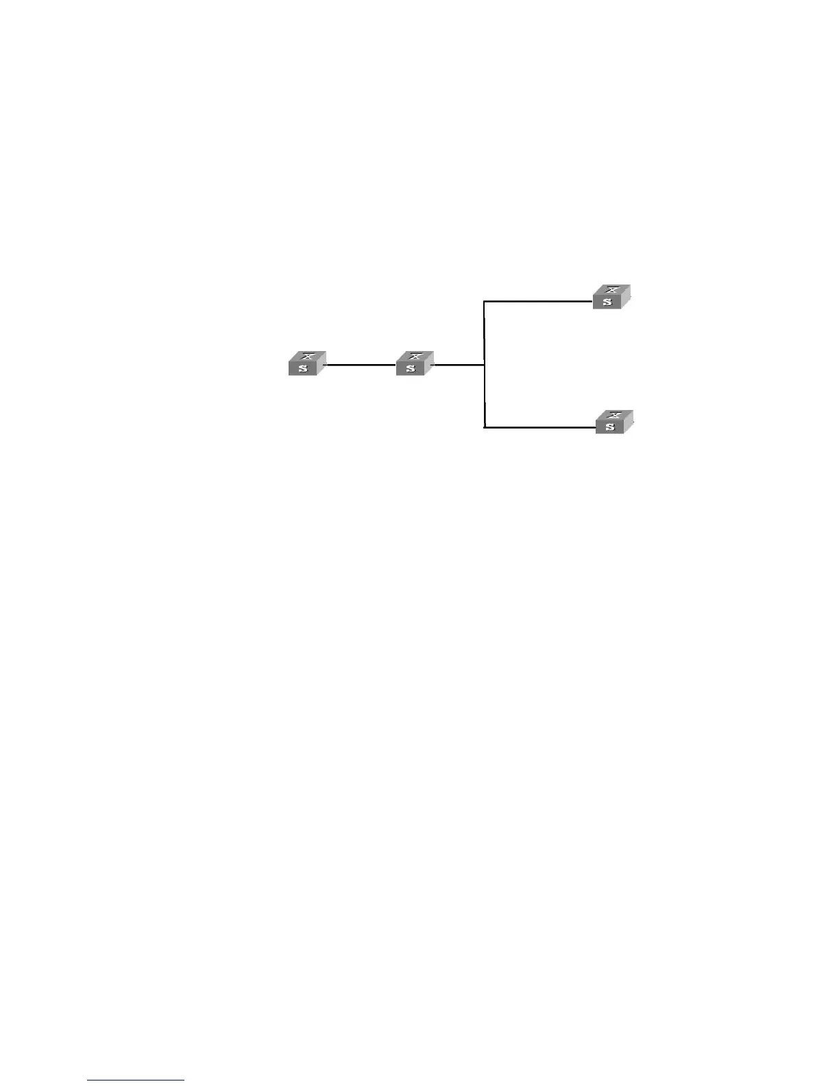
Figure 88 Network diagram for NTP multicast mode configuration
Configuration procedure
1 Configure Switch3.
# Enter system view.
<Switch3> system-view
[Switch3]
# Enter VLAN-interface2 view.
[Switch3] interface Vlan-interface 2
# Set Switch3 to a multicast server.
[Switch3-Vlan-interface2] ntp-service multicast-server
2 Configure SW4500-1.
# Enter system view.
<SW4500-1> system-view
[SW4500-1]
# Enter Vlan-interface2 view.
[SW4500-1] interface Vlan-interface 2
# Set SW4500-1 to a multicast client.
[SW4500-1-Vlan-interface2] ntp-service multicast-client
3 Configure SW4500-2.
# Enter system view.
<SW4500-2> system-view
[SW4500-2]
# Enter Vlan-interface2 view.
[SW4500-2] interface Vlan-interface 2
# Set SW4500-2 to a multicast client.
[SW4500-2-Vlan-interface2] ntp-service multicast-client
After the above configurations, SW4500-1 and SW4500-2 respectively listen to
multicast packets through their own Vlan-interface2, and Switch3 advertises
multicast packets through Vlan-interface2. Because SW4500-2 and SW4500-3 do
not share the same network segment, SW4500-2 cannot receive multicast packets
Switch 3
-
2
Switch 4
3.0.1.31/24
3.0.1.32/24
1.0.1.31/24
Vlan-interface 2
Vlan-interface 2
Vlan-interface 2
3.0.1.31/24
3.0.1.32/24
1.0.1.31/24
-
Vlan-interface 2
Vlan-interface 2
SW4500 -1
3.0.1.31/24
3.0.1.32/24
1.0.1.31/24
-
-
-
3.0.1.31/24
3.0.1.32/24
1.0.1.31/24
-
-
-
-
SW4500
3.0.1.31/24
3.0.1.32/24
1.0.1.31/24
-
-
-
3.0.1.31/24
3.0.1.32/24
1.0.1.31/24
-
-
-
-
3.0.1.31/24
3.0.1.32/24
1.0.1.31/24
-
-
-
3.0.1.31/24
3.0.1.32/24
1.0.1.31/24
-
-
-
-
Vlan
 Loading...