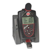
Docking station components
The table below explains the EdgeDock1 or EdgeDock5 LED indicators, power connector, USB
connector, and contact pins.
Table 2-2: EdgeDock1 and EdgeDock5 components
EdgeDock1 or EdgeDock5
The EdgeDock1 and EdgeDock5 are powered by a 12-volt charger adapter.
Figure 2-5 illustrates the assembly of the charger adapter and the plug adapter. It slides into place by
guiding it down the back cavity (opening) of the power supply.
NOTE: the example is a typical adapter which may be different than the one you are using.
Mechanically, it will function similarly.
Figure 2-5: Attaching the charger adapter with the plug adapter
Identifies if the dosimeter is “charging” or “fully charged”. A red blinking
LED indicates the dosimeter is charging. A solid green LED equates to a
fully charged dosimeter.