ACS 160 User’s Manual 75
Group 26: Motor Control
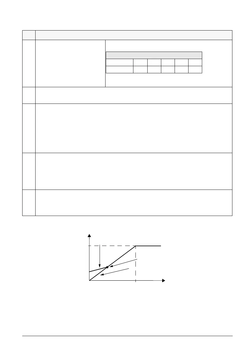
Figure 12 Operation of IR compensation
Code Description
2603 IR COMPENSATION
IR compensation voltage at 0 Hz.
Note! IR compensation should be
kept as low as possible to prevent
overheating. Refer to Table 3.
Table 3 Typical IR compensation values.
2604 IR COMP RANGE
IR compensation range. Defines frequency after which IR compensation is 0 V.
2605 LOW NOISE
Motor acoustical noise option.
0 =
OFF
Standard (switching frequency 4 kHz).
1 =
ON(1)
Low noise (switching frequency 8 kHz).
Note! When the low noise setting is used, the maximum loadability must be derated, see reference section
N.
2606 U/f RATIO
U/f ratio below field weakening point.
1 =
LINEAR
2 = SQUARE
Linear is preferred for constant torque applications, Square for centrifugal pump and fan applications.
(Square is more silent for most operating frequencies.)
2607 SLIP COMP RATIO
A squirrel-cage motor will slip under load. The slip can be compensated by increasing the frequency as the
motor torque increases. This parameter defines the gain for the slip. 100 % means full slip compensation;
0 % means no slip compensation.
400 V Units
P
N
/ kW 0,55 0,75 1,1 1,5 2,2
IR comp / V 33 30 27 25 23
IR compensation
No compensation
Field
f (Hz)
U
N
U (%)
IR compensation range
weakening
point
 Loading...


