ACS 160 User’s Manual 79
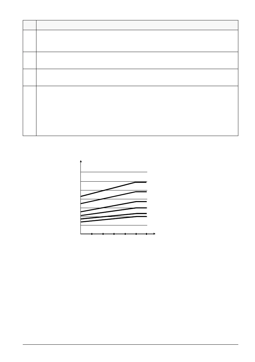
Figure 16 Thermal protection trip times when parameters 3005 MOT THERM TIME, 3006 MOT LOAD
CURVE and 3007 ZERO SPEED LOAD have default values.
3015 UNDERLOAD CURVE
This parameter provides five selectable curves shown in Figure 17. If the load drops below the set curve for
longer than the time set by parameter 3014, the underload protection is activated. Curves 1...3 reach
maximum at the motor rated frequency set by parameter 9907
MOTOR NOM FREQ.
3022 AI1 FLT LIMIT
Fault level for analogue input 1 supervision.
See parameter 3001
AI<MIN FUNCTION.
3023 AI2 FLT LIMIT
Fault level for analogue input 2 supervision.
See parameter 3001
AI<MIN FUNCTION.
3024 MOT THERM MODE
2 =
USER MODE
In this mode the user can define the operation of thermal protection by setting parameters 3005 MOTOR
THERM TIME, 3006 MOT LOAD CURVE, 3007 ZERO SPEED LOAD and 3008 BREAK POINT.
3 =
THERMISTOR
Motor thermal protection is activated with an I/O signal based on motor thermistor. This mode requires a
motor thermistor or break contact of a thermistor relay connected to terminal X4. See Reference Section O.
When overtemperature is detected, the drive stops if the parameter 3004
MOTOR THERM PROT is set to 1
(
FAULT).
Code Description
I
O
/ I
N
f
O
/ f
BRK
I
O
= output current
I
N
= nominal current of the motor
f
O
= output frequency
f
BRK
= break point frequency (parameter 3008 BREAK POINT)
60 s
90 s
180 s
300 s
600 s
∞
3.5
3.0
2.5
2.0
1.5
1.0
0.5
Tr i p t i m e
0
0 0.2 0.4 0.6 0.8 1.0 1.2