16 Control panel overview
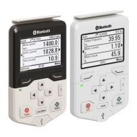
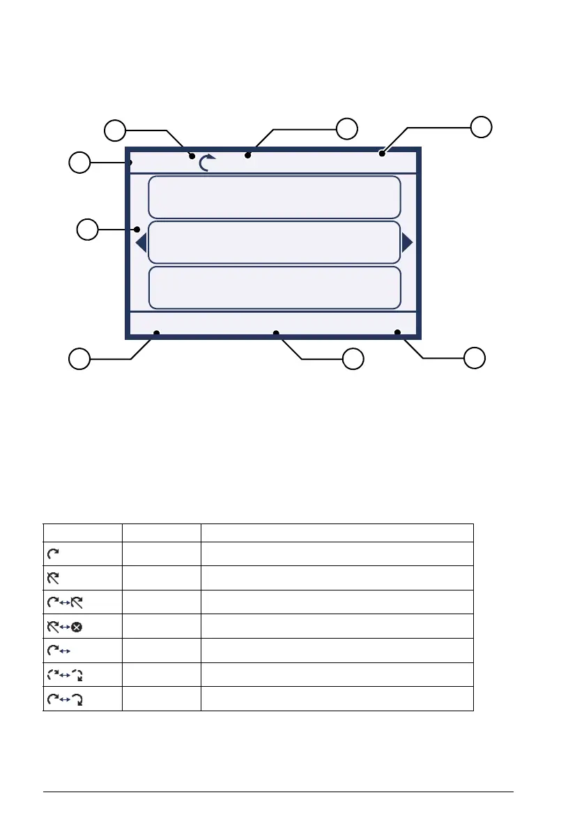
Display
In most views, the following elements are shown on the display:
1. Control location: Indicates how the drive is controlled:
• Local: The drive is in local control, ie, controlled from the control panel.
• Remote: The drive is in remote control, ie, controlled through I/O or fieldbus.
• (Remote): The drive is in remote control (as above), but some commands
(such as start, stop, direction change or reference) are configured to be
controlled by the control panel.
2. Status icon: Indicates the status of the drive and the motor. The direction of the
arrow indicates forward (clockwise) or reverse (counter-clockwise) rotation.
Note: For non-rotating driven equipment, the numbers 1 and 0 are used to indicate
that the drive is running or stopped, respectively.
Status icon Animation Drive status
- Stopped
- Stopped, start inhibited
Blinking Stopped, start command given but start inhibited
Blinking Faulted
Blinking Running, at reference, but the reference value is 0
Rotating Running, not at reference
Rotating Running, at reference
Motor speed
Rpm
Motor current
A
Flow rate
m
3
/s
0.0
0.0
0.0
Options Menu
Local Pump A 0.0 Rpm
17:15
1
2
3
5
6
6
7
4
Assistant Panel Guide Rev B.book Page 16 Tuesday, April 10, 2012 12:08 PM
 Loading...