Control panel overview 19
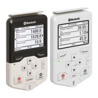
Status LED
The control panel has a status LED that indicates if there are any faults or warnings
present. The table below shows the meaning of the LED indications.
For further information on fault and warning indications, see Identifying error and
warning messages on page 45.
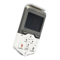
USB connector
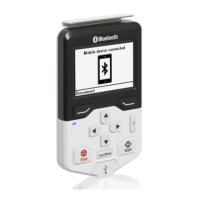
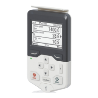
The USB connector is used for connecting the control panel to a PC. When
connected, the control panel acts as an USB adapter for data transfer between the
PC tool and the drive. It is also possible to transfer data between the PC and the
control panel through the USB connection.
RJ-45 connector
The RJ-45 connector is used to electrically connect the control panel to the drive.
Mechanical connection is achieved with the clip on the top.
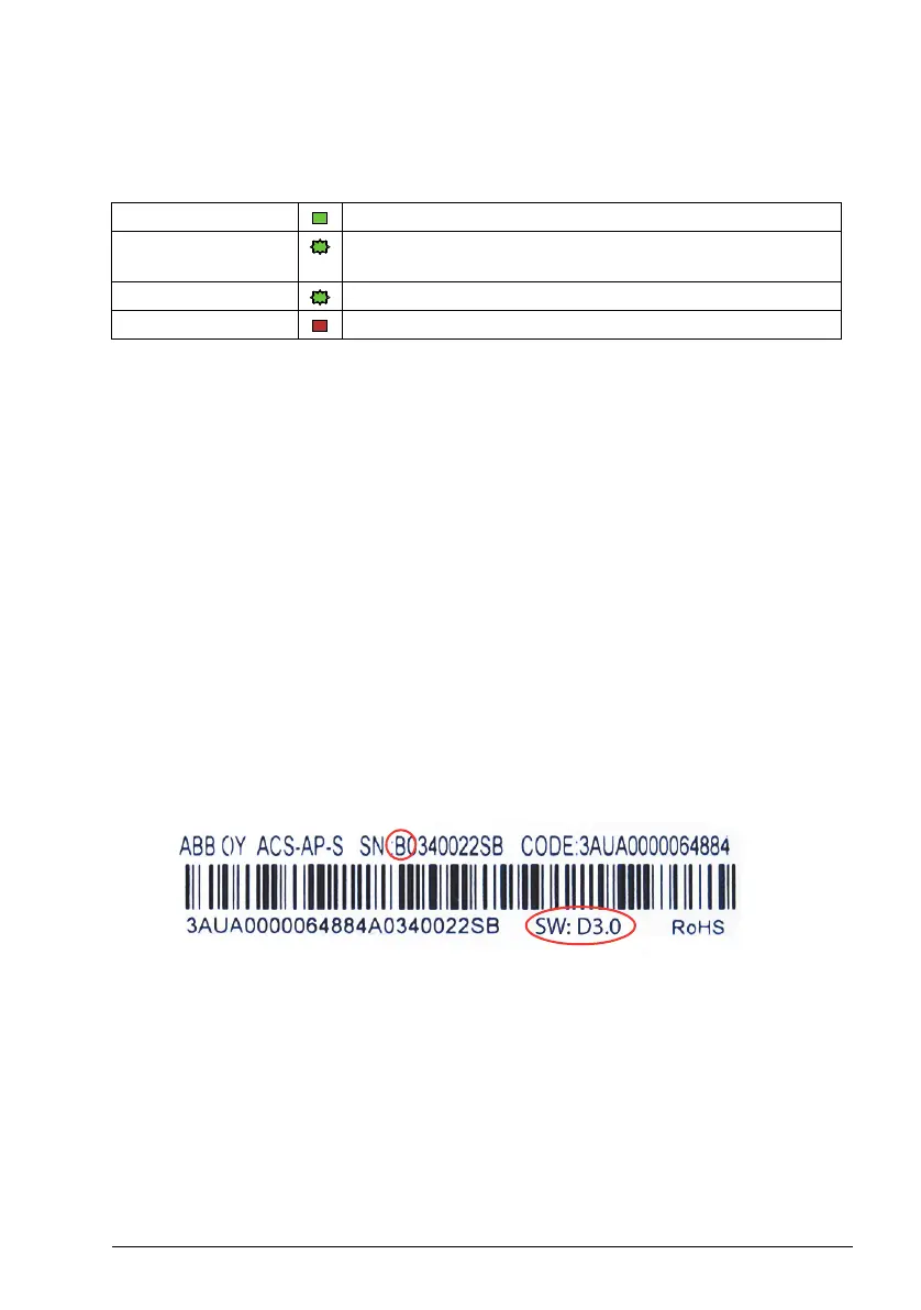
Type code label
The type code label contains revision information. The revision letter and the software
version of the control panel are highlighted in the image below.
Battery cover
Underneath the cover there is a compartment for the battery that powers the real-time
clock of the control panel.
Green, continuous The drive is functioning normally.
Green, flickering Data is transferred between the PC tool and drive through the
USB connection of the control panel.
Green, blinking There is an active warning in the drive.
Red, continuous There is an active fault in the drive.
Assistant Panel Guide Rev B.book Page 19 Tuesday, April 10, 2012 12:08 PM
 Loading...