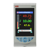
ControlMaster CM30, CM50 and CMF310
Universal process controllers,
1
/4,
1
/2 DIN and fieldmount 7 Advanced Level
80 IM/CM/ED–EN Rev. X
…Functions
Linearizer 1 (2) A 20-breakpoint (custom) linearizer. Custom linearizers are applied by:
1. Selecting an analog source as the input to the linearizer.
2. Selecting the custom linearizer output as the source to be
displayed.
The engineering range and units of the input source are assigned to the
custom linearizer output.
Source 1 (2) Selects the input source to be linearized – see Appendix A, page 104 for description of
sources.
Lin 1 (2)
Breakpoints
Breakpoint
Selects the breakpoint to be configured.
X
X is input to the linearizer expressed as a % of the electrical range.
Y
Y is output expressed as a % of the engineering range.
Once configured, a custom linearizer must be soft-wired to an input or output using the
custom template feature – see Section 7.1, page 34.
Delay Timer 1 (2) 2 Delay timers are provided. The delay timer is triggered by the rising edge of its assigned
source. An internal timer is started and, when the timer reaches the set Delay Time, its
output goes high for the On Time that is configured. After the delay time is triggered it
ignores any further transitions of the source input until the end of this delay timer cycle (until
the end of the On Time).
Source 1 (2) The source signal used to trigger the delay timer. Trigger
occurs on rising edge of the signal – see Appendix A, page
104 for description of sources.
Delay Time The delay (in seconds) between the trigger received and the output of the delay timer going
high.
On Time The length of time in seconds the delay timer output is held in the high state.
0
10
20
30
40
50
60
70
80
90
010
20
30 40 50 60 70 80 90
 Loading...


