II K 4-35
Overview of Software
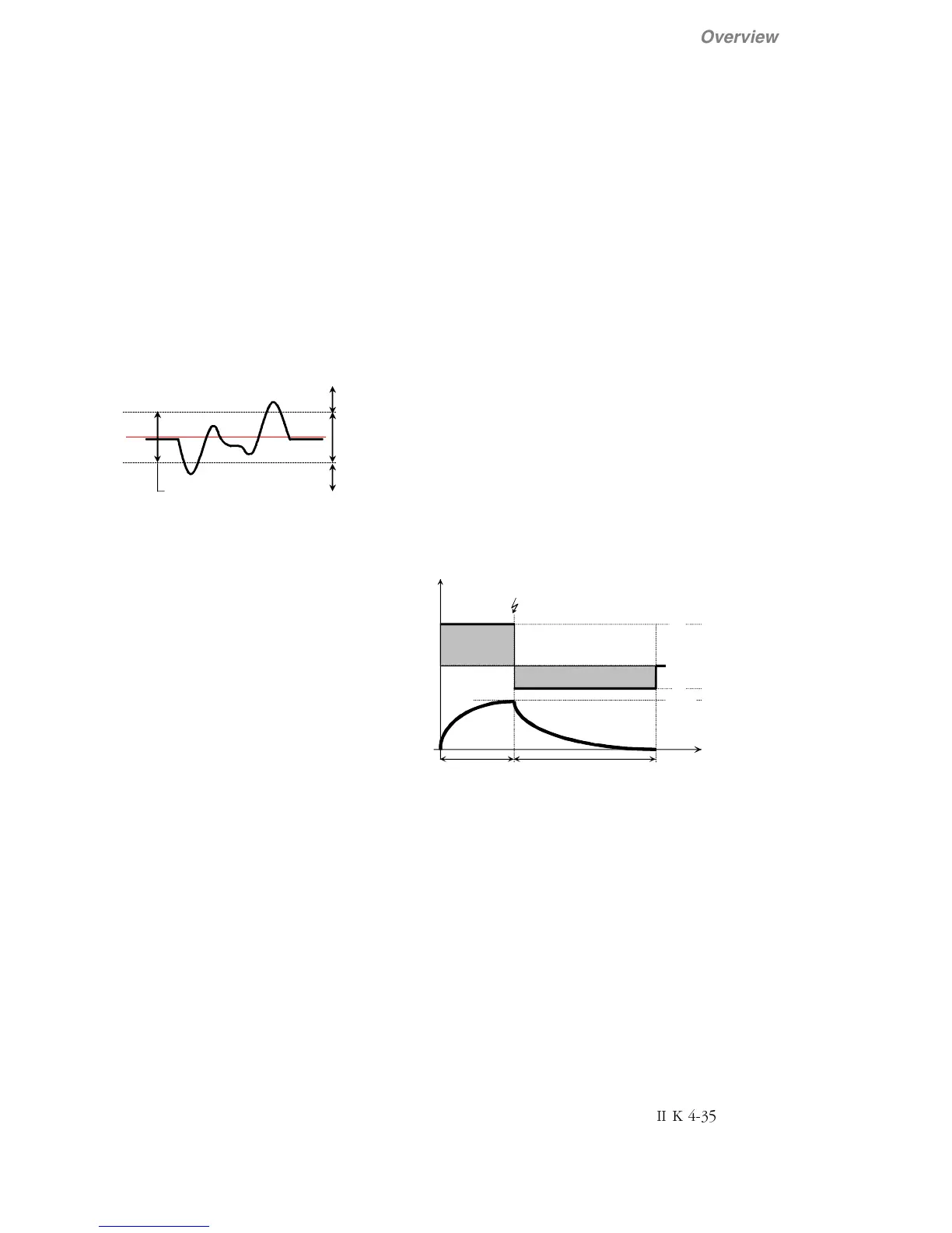
6 = Lim Trq Ctr (Window Control Mode)
The idea of Window Control Mode is to deactivate the
speed control as long as the speed deviation remains
within the window. This allows the torque reference to
affect the process directly.
In master / follower drives, where the follower section
is torque controlled, the window control is used to
keep the speed deviation of the section under control.
If the speed deviation (window) is greater than ±50 rpm
the follower changeover to speed control mode and
brings the speed difference back to the window.
The window control is activated by setting Cur Contr
Mode (3.14) = Lim Trq Ctr.
torque controlled
speed
reference
speed actual
permitted speed deviation between speed
reference and speed actual is +/- 50 rpm
speed controlled
speed controlled
I
2
t function
The DCS400 is equiped with an I
2
t-protection for the
motor, which can be enabled if required. Parameter
Arm Cur Nom (1.01) is the 100% value for the
current. All current depending values are related to
this parameter.
The I
2
t-function is enabled if the parameters Over-
load Time (3.05) and Recovery Time (3.06) are set
to a value higher than 0 seconds and the overcurrent
in parameter Arm Cur Max (3.04) is set to a value
higher than the Arm Cur Nom (1.01).
The function is disabled if the parameter Overload
Time (3.05) = 0 s, or Recovery Time = 0 s, or Arm
Cur Max (3.04) = Arm Cur Nom (1.01).
If the recovery time is set to a value too low compared
to the overload time, the alarm message Par Setting
Conflict (A16) "Recovery Time to low" is generated.
In addition to the overcurrent parameters the refer-
ence limititations Torque Lim Pos (3.07) and Torque
Lim Neg (3.08) have to be set.
It has to be ensured that the parameterized overload
times correspond to the overload capability of motor
and drive. This has already to be taken into account
during the selection process of the drive system.
Ia (%)
(3.04)
(1.01)
(3.05)
(3.06)
t
A6
Ia
nom
=100%
Ia
red
Ia
max
Arm Cur reduced
overload phase
Ia > 100%
Recovery phase Ia < 100%
Integral
Limit