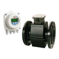
Specifications
D184B140U02 FSM4000 121
12.3 Transmitter S4
Flow range
Any flow range whose 100% value
corresponds to a flow velocity between 0.5 m/s
and 10 m/s can be selected.
Minimum
conductivity
≥ 20 µS/cm standard
≥ 20 µS/cm with preamplifier
≥ 5 µS/cm with preamplifier
≥ 0.5 µS/cm with preamplifier
DN 10 ... 1000
(3/8 ... 40“)
DN 1 ... 8
(1/25 ... 5/16“)
DN 1 ... 1000
(1/25 ... 40“)
DN 10 ... 1000
(3/8 ... 40“)
Reproducibility
(measurement
period
= 100 s)
DN 1 ... 2:
≤ ± (0.3% of meas. value + 0.04% of Q
maxDN
)
DN 3 ... 1000:
≤ ± (0.1% of meas. value + 0.01% of Q
maxDN
)
Response time 1 = 70 ms (0 ... 66 %) "Fast" mode
1
= 200 ms (0 ... 66%) "Standard" mode /
piston pump
Supply power
U = 100 ... 230 V, 50/60 Hz
U
rat
= 85 ... 253 V, 50/60 Hz
50/60 Hz ± 6%
20,4 ... 26.4 V AC,
20,4 ... 31.2 V DC, ripple ≤ 5%
Power
S ≤ 45 VA (flowmeter sensor including
transmitter
Ambient
temperature
-20 ... 60 °C (-4 ... 140 °F)
Storage
Temperature
-20 ... 80 °C (-4 ... 176 °F)
Protection Class
per EN 60529
IP 67, NEMA 4X
Relative humidity
according to 60068-2-30
classification of environmental conditions,
natural factors, temperature and air humidity.
No effect under the following conditions:
Temperature in range from 25 ... 55 °C
(77 ... 131 °F) and a relative humidity of
94 ... 97%.
Shock and
vibration
resistance
according to 60068-2-6
grouping of devices according to table C2 for
general industry applications. No additional
effect on the following levels of vibration:
Frequency range 10 ... 55 Hz; amplitude max.:
0.15 mm
Cable entry
points
M20 x 1.5; NPT ½" option; PF ½" option
Galvanic
isolation
The current output, pulse output, switch
contact input and switch contact output are
galvanically isolated from the input circuit and
from each other.
Design
Field-mount housing made of cast aluminum per DIN 1725, painted.
Paint coat is 80 µm thick. Lower section (RAL 7012), upper section
(RAL 9002). Weight, approx. 3.3 kg.
Signal cable / coil cable
Max. cable length between flowmeter sensor and transmitter is: 50 m
for the standard design and versions with automatic zero return, from
DN 10 (3/8") and from 20 µS/cm. 200 m for designs with preamplifier.
A 10 m signal cable is included with the flowmeter. If more than 10 m
is required, the cable can be purchased using order number
D173D025U01 or D173D147U01.
 Loading...
