Electrical connections
40 FSM4000 D184B140U02
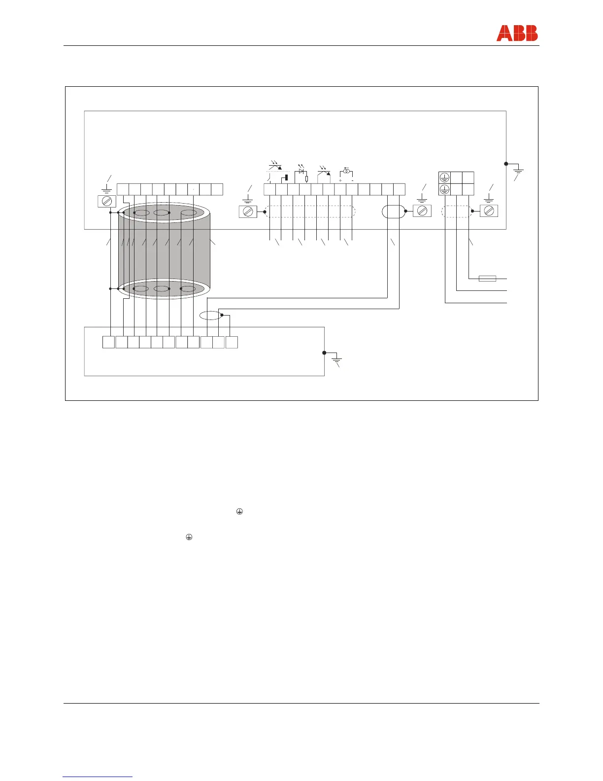
5.4 Terminal connection diagrams
Standard DN 10 ... DN 1000 (3/8 ... 40")
S4 transmitter (wall mount housing)
G00595
SE
M1
N
2- 1+
L
M3
51 52 81 82 41 42 31 32
SE
3
3
2
2
1S
1S
3
3A
16
16
2S
2S
76
1
1
1
1
1
1
1
2
3
4
5
M1
M3
1
6
7
8
12
13
119
11 11 14 15
10
Flowmeter sensor
Fig. 36: Connection diagram: Flowmeter sensor standard DN 10 ... DN 1000 (3/8 ... 40")
1 Functional ground (busbar)
2 Pulse output
1)
3 Contact input
1)
4 Contact output
1)
5 Current output
1)
6 Magnet coil cable:
shielded 2 x 1 mm
2
CE Typ 227 TEC 74
ABB order no. D173D147U01, 10 m included in shipment,
standard
7 Supply power
Low voltage: 100 ... 230 V AC, terminals L, N,
Low voltage: 20.4 ...26.4 V AC;
Low voltage: 20.4 ... 31.2 V DC
Low voltage: Terminals 1+, 2-,
Frequency: 47 Hz ≤ f ≤ 53 Hz; 50 Hz supply power
Frequency: 56 Hz ≤ f ≤ 64 Hz; 60 Hz supply power
8 Steel shielding
9 Aluminum foil
10 Yellow
11 Shield
12 Blue
13 Red
14 White
15 Shielded signal cable: ABB order no. D173D025U01, 10 m
included in shipment
1) See the section "Connection examples for peripherals" in the operating instructions and/or on the data sheet
Comment:
We recommend that shielded output cables be used with the shields connected to the functional ground at one end.

 Loading...


