NoteAction
xx0600002734
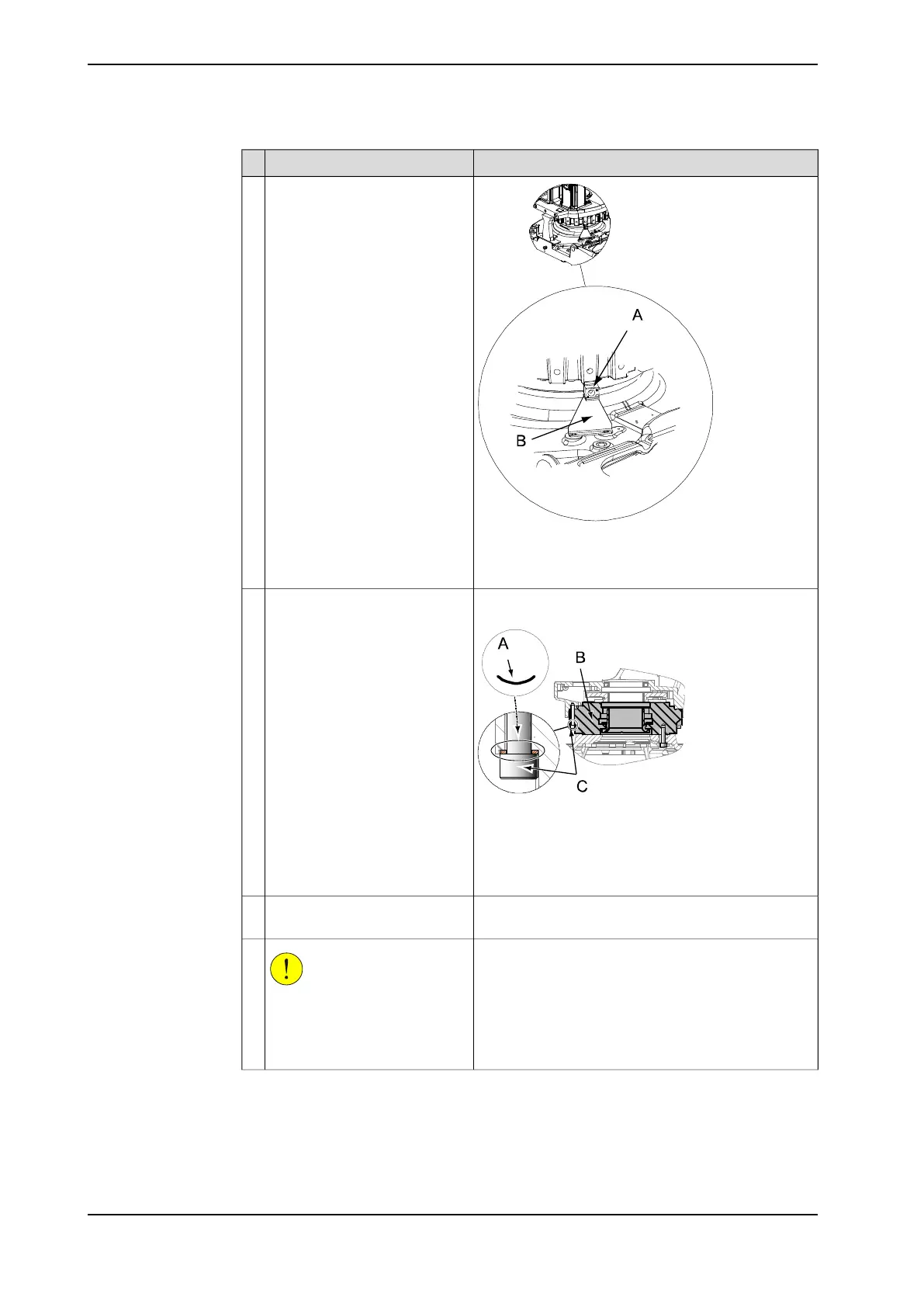
Remove the block for calibration
and calibration plate axis 1 from
the bottom of the frame.
10
• A: Block for calibration
• B: Calibration plate axis 1
Shown in the figure Location of arm system on
page 207.
xx0600003070
Unfasten the arm system from
the base by unscrewing its 24
attachment screws.
11
Parts:
• A: Serrated lock washer
• B: Gearbox axis 1
• C: Attachment screws M12x80
Art. no. is specified in section Required equipment on
page 208.
Fit two guide pins in two oppos-
ite screw holes.
12
CAUTION
The complete arm system
weighs 1330 - 1520 kg! All lifting
equipment used must be sized
accordingly!
13
Continues on next page
212 Product manual - IRB 6660
3HAC028197-001 Revision: S
© Copyright 2007-2018 ABB. All rights reserved.
4 Repair
4.3.5 Replacement of complete arm system
Continued
 Loading...


