Operation Manual / Power2 800-M / 4 Product description
Page 3 /
© Copyright 2016 ABB. All rights reserved.
1 Introduction
1.1 Power2 layout and function
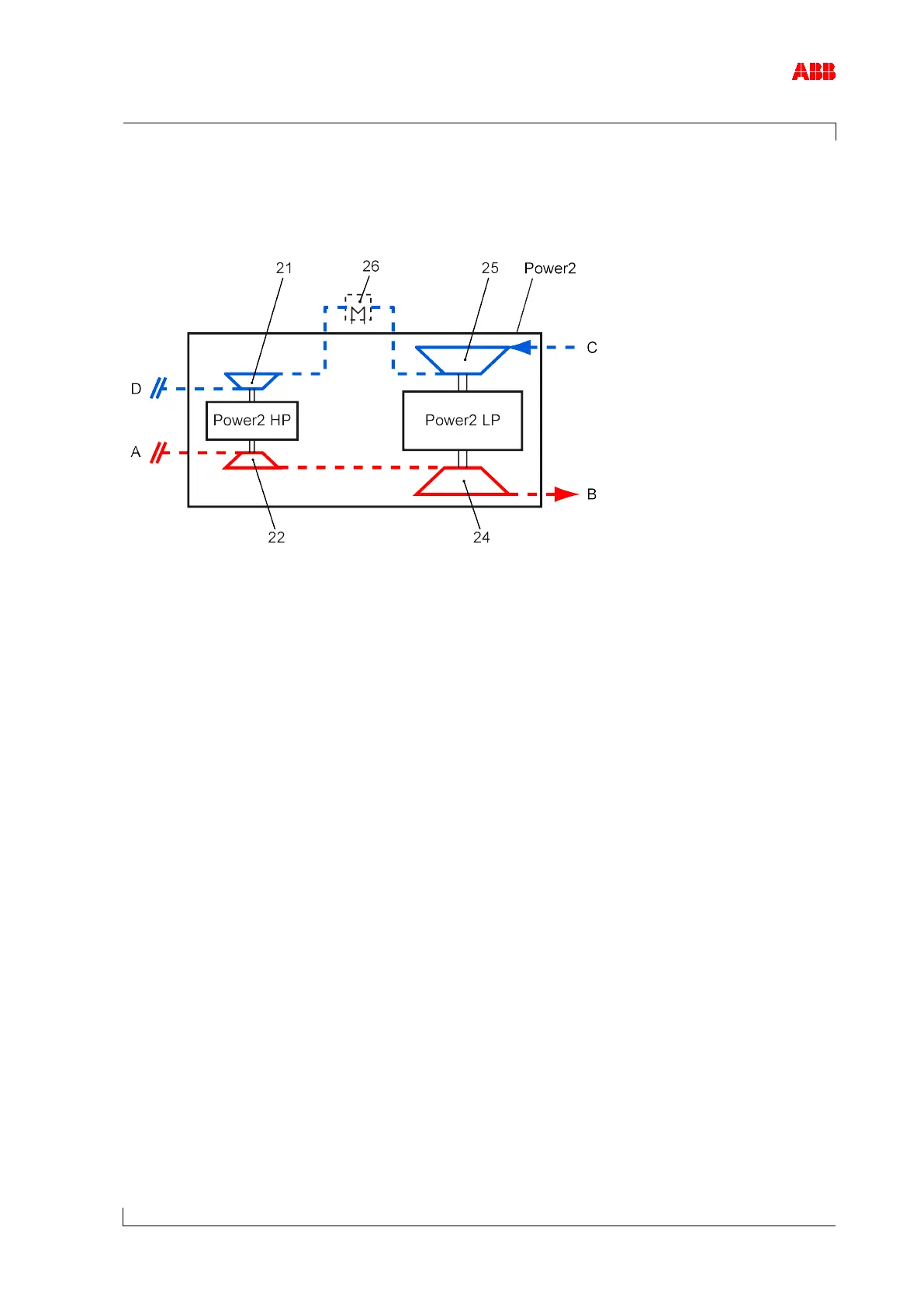
Figure 1: Power2 layout and function
Power2 Two-stage turbocharging 21 HP compressor
Power2 LP Low-pressure stage 22 HP turbine
Power2 HP High-pressure stage 24 LP turbine
A Exhaust gas inlet from internal
combustion engine
25 LP compressor
26 Intercooler
C Air or air/gas mixture inlet
D Air or air/gas mixture outlet and supply
to the charge air cooler
- - - Not included in the ABB Turbo Sys-
tems scope of delivery
The diagram shows the position of the low-pressure (Power2 LP) and high-pressure stage
(Power2 HP) within two-stage turbocharging (Power2). The low-pressure stage is always op-
erated in combination with a high-pressure stage connected in series. The two-stage turbo-
charging (Power2) supplies the engine with the air volume and associated charging pressure
required for operation.
Here, the exhaust gases of the internal combustion engine flow through the turbine (22) of the
high-pressure stage and then to the turbine (24) of the low-pressure stage. The compressor
(25) of the low-pressure stage sucks in fresh air or the air/gas mixture, respectively. This pre-
compressed air or air/gas mixture flows through the intercooler (26) into the compressor (21)
of the high-pressure stage. Here the air or air/gas mixture is compressed further and leaves
the two-stage turbocharging (Power2) in the direction of the charge air cooler.