Operation Manual / Power2 800-M / 4 Product description
Page 31 /
© Copyright 2016 ABB. All rights reserved.
6.3.3 Wet cleaning of turbine blades and nozzle ring
Cleaning procedure
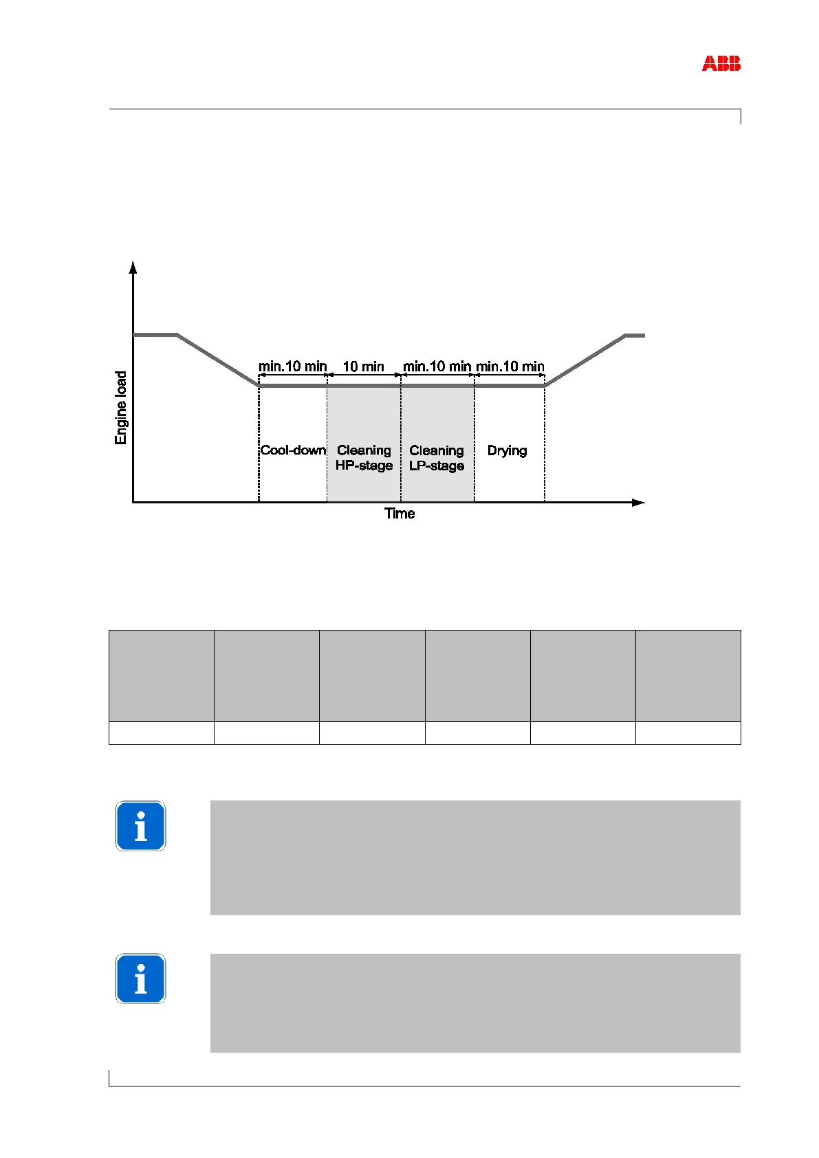
The individual phases of the turbine cleaning procedure are shown in the following illustration.
Figure 12: Load/time chart
1. Cool down phase
Reduction of the engine load to the operating point for turbine cleaning and subsequent
maintenance of the holding time according to the specifications in the following table.
Gas pulse at
the inlet in the
HP stage
[N/m
2
]
Gas pulse at
the inlet in the
LP stage
[N/m
2
]
Max. gas inlet
temperature
when starting
cleaning
[°C]
Holding time at
reduced load
[min]
Table 10: Operating point for turbine cleaning
Algorithm for the gas pulse
For an optimum cleaning result, the gas pulse adopted when designing the
cleaning process should be set via the control system on the engine side.
The algorithm for the gas pulse is specified in the section Calculation of the
gas pulse [➙ 34]. If this is not possible, the specified engine load point is to
be set as an approximation.
Due to the thermomechanical stress of the turbine casing, the gas inlet tem-
perature should not exceed the specified maximum temperature before start-
ing cleaning. If this is the case, the engine load is to be lowered until the
permissible temperature is reached.