Operation Manual / Power2 / 1 Introduction
1 Introduction / 1.4 Power2 layout and function
© Copyright 2017 ABB. All rights reserved. HZTL4004_EN Revision D June 2017
1.4 Power2 layout and function
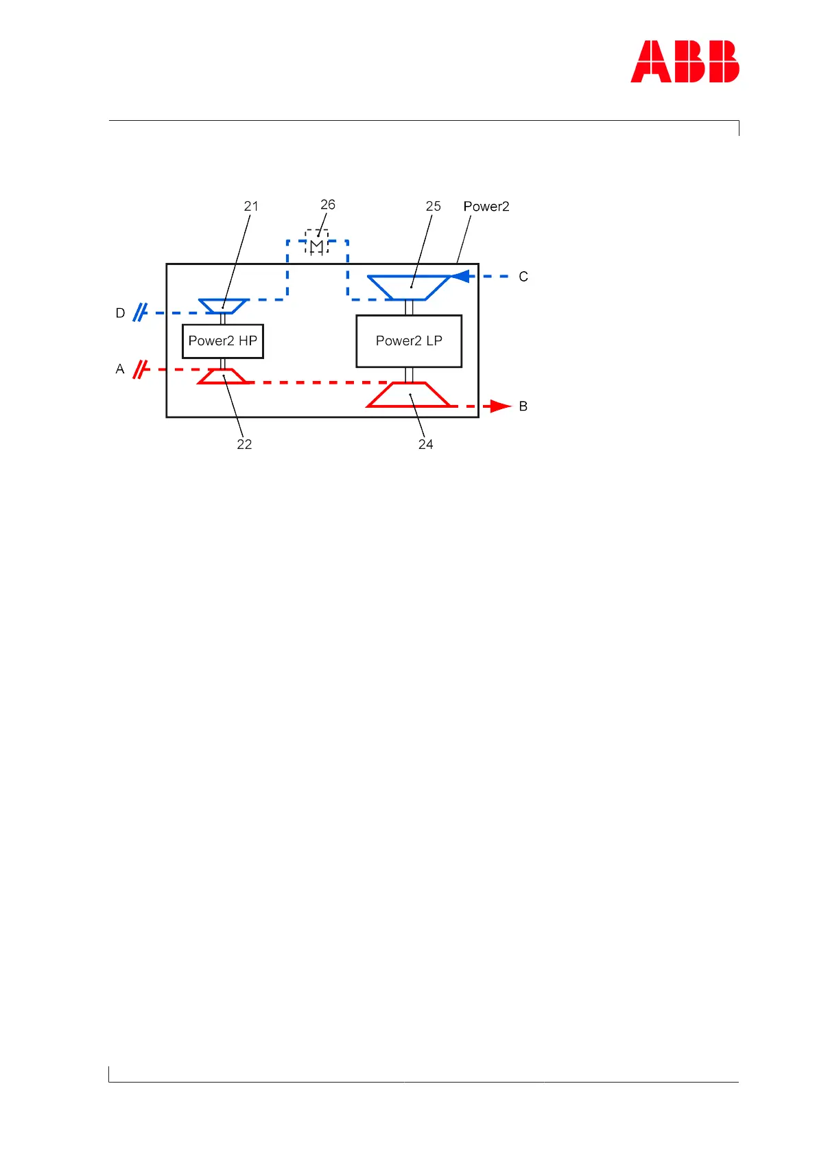
Fig.1: Power2 layout and function
Power2 Two-stage turbocharging 21 HP compressor
Power2 LP Low-pressure stage 22 HP turbine
Power2 HP High-pressure stage 24 LP turbine
A Exhaust gas inlet from internal combus-
tion engine
25 LP compressor
B Exhaust gas outlet 26 Intercooler
C Air or air/gas mixture inlet
D Air or air/gas mixture outlet and supply
to the charge air cooler
- - - Not included in the ABB Turbo Sys-
tems scope of delivery
The diagram shows the position of the low-pressure (Power2LP) and high-pressure stage
(Power2HP) within two-stage turbocharging (Power2). The low-pressure stage is always op-
erated in combination with a high-pressure stage connected in series. The two-stage tur-
bocharging (Power2) supplies the engine with the air volume and associated charging pres-
sure required for operation.
Here, the exhaust gases of the internal combustion engine flow through the turbine (22) of
the high-pressure stage and then to the turbine (24) of the low-pressure stage. The com-
pressor (25) of the low-pressure stage sucks in fresh air or the air/gas mixture, respectively.
This precompressed air or air/gas mixture flows through the intercooler (26) into the com-
pressor (21) of the high-pressure stage. Here the air or air/gas mixture is compressed fur-
ther and leaves the two-stage turbocharging (Power2) in the direction of the charge air
cooler.
Page 5 / 8