Manual Power Quality Filter PQFM The PQF-Manager user interface 143
4
If the event reported is a fault, which is considered critical by the system, a ‘Critical’
indication will appear on the screen.
5
Fault description list if the event was a fault.
Table 53 and Table 54 give an overview of the possible faults that can be reported.
When entering the ‘Event logging’ window, the most recent event is always displayed.
Use the arrow keys to scroll through the event list. Use any other key to quit the menu.
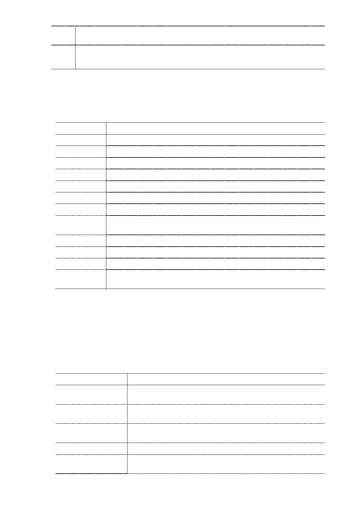
Table 52: Overview of the events that can be recorded
No storable event has occurred yet
The filter controller has been reset
A filter start has been requested
A filter stop has been requested
The DSP controller has reported a fault
controller has reported a faul
A user attempt to clear a fault has been recorded (by validating the ‘ACK.
FAULT’ option on the PQF-Manager
The system detects no more faults
The system has detected a power outage
r firmware upgrade (attempt) has been recorded
An internal stop command coming from the DSP controller has been
recorded
From Table 52 it can be seen that both the DSP controller and the µcontroller can record
faults. Where the faults reported by the µcontroller are predominantly relating to a
control board failure, the faults reported by the DSP relate predominantly to the filter
interacting with the installation. Table 53 gives an overview of the faults that can be
reported by the DSP controller. The list is in alphabetical order.
Table 53: Overview of the faults that can be reported by the DSP controller
The automatic CT detection procedure has encountered a problem
during the identification process.
The DSP has detected an inconsistent set of commissioning
parameters
The DC software over voltage protecti
on has been triggered (Cf.
the detailed manuals for limit values).
The DC hardware over voltage protection has been triggered.
The DC over voltage protection of the capacitors in the positive
stack has been triggered.