78 Electrical design and installation Manual Power Quality Filter PQFM
connected to the supply,
error appears
present for 3 minutes
Otherwise, remains
closed
Closes when error present for 3
minutes
Otherwise, remains open
connected to the supply,
error disappears
closes when error
disappears
When closed before,
remains closed
When closed before, opens when error
disappears
When open before, remains open
Figure 60 shows an example of an alarm contact cabling scheme using the NC alarm
contact. Using this scheme the bulb B will be on when the power supply to the filter is
interrupted or the filter trips due to an error. Otherwise the bulb will be off.
15
16
(a)
17
(a)
external
power
supply
alarm indicator
Remark:
(a)
Right hand terminal block when looking from rear, counting from top to
Figure 60: Alarm bulb cabling scheme using the NC alarm contact on
the PQF-Manager
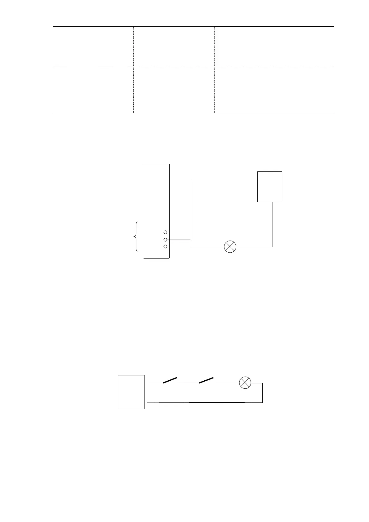
When the filter system consists of multiple master-units and an alarm contact is needed
to signal when the complete system is off, then the NC alarm contacts of all the master
units have to be cabled in series. An example is given in Figure 61 for 2 master filters.
Note: Contacts drawn in non-alarm position
230 Vac
external
power
supply
NC Alarm
contact of
master 1
NC Alarm
contact of
master 2
Alarm bulb
Figure 61: Cabling of the alarm status of a multi-unit filter consisting of masters only, using the
NC alarm contact on each filter.
In the Figure 61, the alarm bulb will be activated when both master units are in alarm.