ProcessMaster FEP610, HygienicMaster FEH610 | OI/FEP610/FEH610-EN Rev. B 25
5.5.5 Electrical connection
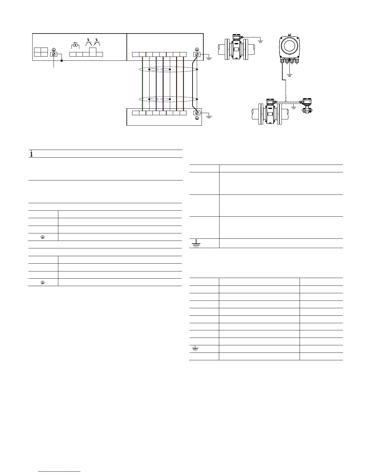
Fig. 36: Electrical connections
A Connections for power supply and outputs B Connections for signal cable (remote mount design only)
Change from one to tw o columns
NOTE
For detailed information about earthing the transmitter and
the sensor, please refer to chapter "Grounding the flowmeter
sensor" on page 19!
Connections for the power supply
AC power supply
Terminal Function / comments
L Phase
N Neutral conductor
PE / Protective earth (PE)
DC voltage supply
Terminal Function / comments
1+ +
2- -
PE / Protective earth (PE)
Connections for outputs
Terminal Function / comments
31 / 32 Active current output
The current output is "active" mode. The source to drive
the 20 mA loop is in-built in the transmitter.
41 / 42 Passive digital output DO1
The output can be configured as a pulse output,
frequency output or switch output on site.
51 / 52 Passive digital output DO2
The output can be configured as a pulse output,
frequency output or switch output on site.
Functional earth
Connections for the signal cable
Only for remote mount design.
Terminal Function / comments Color
FE
Not connected —
3 Measurement potential green
2S Shield for E2 —
E2 Signal line blue
E1 Signal line violet
1S Shield for E1 —
M1 Magnet coil brown
M2 Magnet coil red
Shield —
—
Not connected orange / yellow
G12018
+
-
+
3
M1
2S
E2 E1
1S
3
B
B
≤ 50 m (200 m)
≤ 164 ft (656 ft)
31 32
A
41 42
51
52
1+
2-
PE
+
-
PE
PE
PE
PE
LN
FE
FE
M2
M1
2S
E2 E1
1S M2