26 OI/FEP610/FEH610-EN Rev. B | ProcessMaster FEP610, HygienicMaster FEH610
5.5.6 Electrical data for inputs and outputs
Power supply L / N, 1+ / 2-
AC power supply
Terminals L / N
Operating voltage
100 … 240 V AC (-15 % / +10 %), 47 … 64 Hz
Power consumption
< 20 VA
Inrush current
8.8 A
DC voltage supply
Terminals 1+ / 2-
Operating voltage
24 ... 48V DC (-10 % / +10 %)
Ripple
< 5 %
Power consumption
< 10 W
Inrush current
5.6 A
Current output 31 / 32
Can be configured for outputting mass flow, volume flow.
Fig. 37: Connection example active current output 31 / 32
(I = internal, E = external, R
B
= load)
Current output Active
Terminals 31 / 32
Output signal 4 … 20 mA
Load R
B
0 ≤ RB ≤ 650
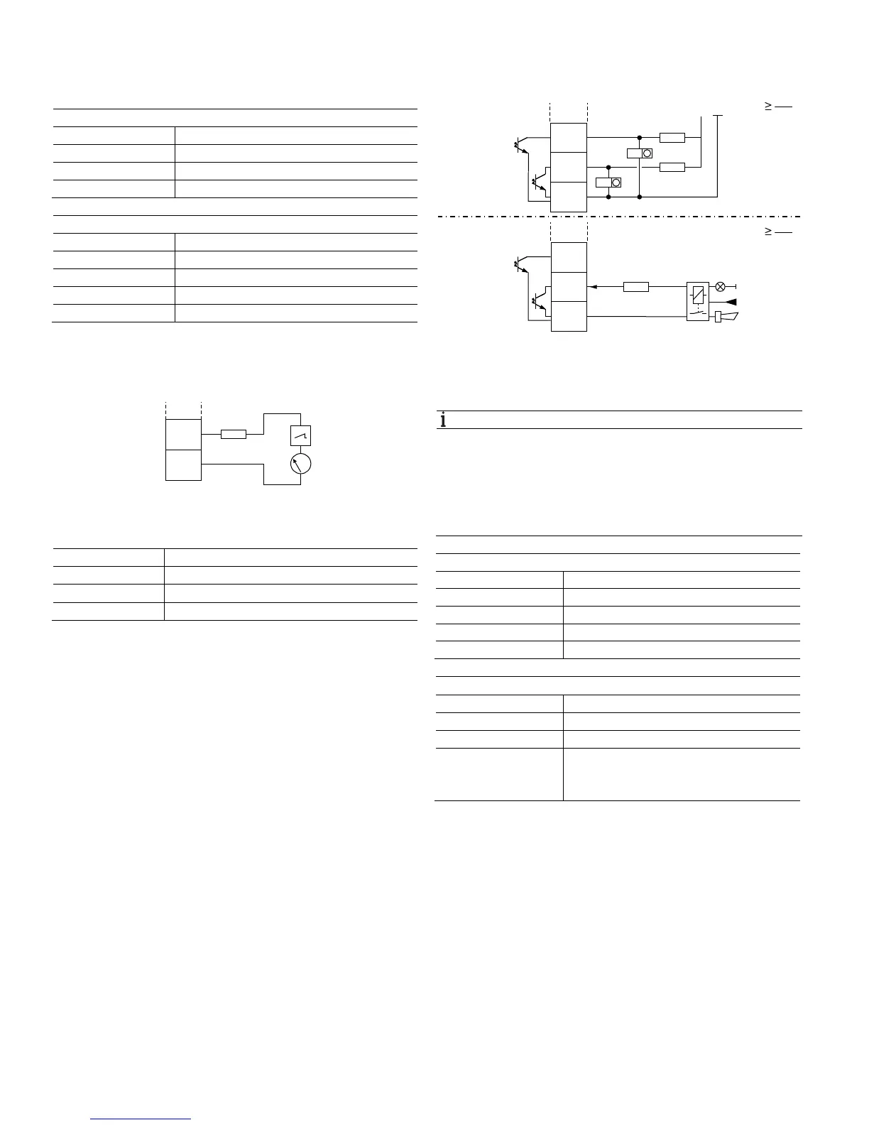
Digital output 41 / 42, 51 / 52
Can be configured as pulse, frequency or binary output.
Fig. 38: Connection example (I = internal, E = external, R
B
= load)
A Passive digital output 41 / 42, 51 / 52 as pulse or frequency output
B Passive digital output 51 / 52 as binary output
NOTE
— Terminals 42 / 52 have the same ground potential.
Digital outputs 41 / 42 and 51 / 52 are not electrically
isolated from each other.
— If you are using a mechanical counter, we recommend
setting a pulse width of ≥ 30 ms and a maximum
frequency of fmax ≤ 3 kHz.
Pulse / frequency output (passive)
Terminals 41 / 42, 51 / 52
U
max
30 V DC
I
max
25 mA
f
max
10.5 kHz
Pulse width 0.1 … 2000 ms
Binary output (passive)
Terminals 41 / 42, 51 / 52
U
max
30 V DC
I
max
25 mA
Switching function Can be configured using software as:
System alarm, empty pipe alarm, max. / min.
alarm, flow direction signaling, others
Change from two to one column
G12037
+31
-32
4 ... 20 mA
IE
R
B
G11597-01
A
R
B
16 ... 30 V
IE
-
51
42/52
+
41
R
B
R
B
51
42/52
41
IE
B
0 V
24 V DC
R
B
U
CE
I
CE
R
B
U
CE
I
CE